• Post Reply Bookmark Topic Watch Topic
  • New Topic
permaculture forums growies critters building homesteading energy monies kitchen purity ungarbage community wilderness fiber arts art permaculture artisans regional education skip experiences global resources cider press projects digital market permies.com pie forums private forums all forums
this forum made possible by our volunteer staff, including ...
master stewards:
  • Nancy Reading
  • Carla Burke
  • r ranson
  • John F Dean
  • paul wheaton
  • Pearl Sutton
stewards:
  • Jay Angler
  • Liv Smith
  • Leigh Tate
master gardeners:
  • Christopher Weeks
  • Timothy Norton
gardeners:
  • thomas rubino
  • Jeremy VanGelder
  • Maieshe Ljin

Solar Tracker setup

 
Rocket Scientist
Posts: 1809
Location: Kaslo, BC
525
building solar woodworking rocket stoves wood heat greening the desert
  • Likes 2
  • Mark post as helpful
  • send pies
    Number of slices to send:
    Optional 'thank-you' note:
  • Quote
  • Report post to moderator
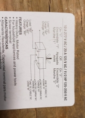
I need some help replacing a bad rotary switch on a solar panel array that has an older single axis  Wattsun tracker. The rotary switch is 2 pole, 6 way. The way its hooked up now allows the tracker motor to turn manually to the left, manually to the right, OFF or in tracker mode. I don't have a replacement rotary switch on hand and thought it could be hooked up much simpler....only have it be in tracker mode. Picture 1 is how it is hooked up now to the rotary switch. Picture 2 is the control board (which controls the tracker). Picture 3 is the solar tracker with the cover off.
The wire coming from the circuit board (which is also connected to the 'eye' or light sensor) provides little bursts of power to the tracker motor so its always pointed at the sun. I made the mistake of thinking that I could bypass the rotary switch entirely and just connect this wire to the solar tracker bus bar but when I did...POOF! The motor turned for about a 1/4 second and then nothing. When I looked at the control board, one of the legs on a diode and also a leg on the Triac were fried. The fuse was just fine of course!
Luckily I had another board to install but sure didn't want something like that to happen again. Time to call on some help.

Some other info: The 27.4V coming from the jct box provides power to make the motor manually turn the panels left or right when the switch is in these positions.

So again, is there any way to hook this up so that I can just leave it in tracker mode and without frying anything more in the process? :)
Any help appreciated!

EDIT- I realize that this is probably not an easy thing to rewire, in particular at a distance with limited info and so I have ordered a switch (hopefully the right one) and see if I can just duplicate the existing one. Let you know how it turns out if there are no replies.
wiring-diagram-for-solar-trackerjpg.jpg
[Thumbnail for wiring-diagram-for-solar-trackerjpg.jpg]
2-control-circuit-board-out-of-my-Wattsun-125-single-axis-tracker..jpg
[Thumbnail for 2-control-circuit-board-out-of-my-Wattsun-125-single-axis-tracker..jpg]
3-solar-tracker.JPG
[Thumbnail for 3-solar-tracker.JPG]
 
Posts: 11
Location: Catskill Mountains, New York
7
  • Likes 1
  • Mark post as helpful
  • send pies
    Number of slices to send:
    Optional 'thank-you' note:
  • Quote
  • Report post to moderator
This is my first post.
I'm an auto mechanic not a solar tech.
I've never messed with one of these.
Now my mind is bothered by it so I want to know what the fix is.
Question 1: Is there a chance the board was fried before you tried to jump it?  Maybe the corrosion on that switch might have bridged a circuit previously and only part of the control circuit is functioning.
Question 2: I'm assuming there is no continuity between A5-A6 as well as between B2-B3. Is that correct?
Question 3: Did you check resistances on the motor end of things via the bus bar?
I have a feeling you were right in hooking up the control board to the bus bar but the control board was already fried when you did.
That's my best guess from across the interwebs.
Good luck.
 
pollinator
Posts: 920
Location: Central Ontario
171
kids dog books chicken earthworks cooking solar wood heat woodworking homestead
  • Likes 1
  • Mark post as helpful
  • send pies
    Number of slices to send:
    Optional 'thank-you' note:
  • Quote
  • Report post to moderator
Can you source a whole replacement controller? I know Alt E still carries the Wattsun... Not much volume on trackers anymore due to panel prices.  The board and switch do not seem powerful enough to run the motor but I can't make out any relays on it. You could probably wire in a series of single switches to replace the rotary making sure only one is ever flipped provided the board is not fried. Have you tried the motor just powered directly? Is it seized which could have caused the controller to die?  I'm looking forward to watching the fix...
Cheers,  David
 
Posts: 400
Location: SW Missouri
86
hugelkultur duck trees chicken pig bee solar wood heat
  • Mark post as helpful
  • send pies
    Number of slices to send:
    Optional 'thank-you' note:
  • Quote
  • Report post to moderator
I agree with David, I don't see any relays, there is no way that board can drive that motor directly. I'm at a loss
 
Posts: 726
Location: Morocco
99
cat forest garden trees solar wood heat woodworking
  • Likes 1
  • Mark post as helpful
  • send pies
    Number of slices to send:
    Optional 'thank-you' note:
  • Quote
  • Report post to moderator
Eric, the Mosfet does the switching. It is the small black 6-legged part on the left (that actually has to contain 4 mosfets).

Gerry, connecting the two wires coming from the circuit board in the schematic to the motor did not work? I would expect that to be the fix…  unless the circuit board senses the rotary switch position, but then it makes no sense for the motor to be connected to it.
 
Posts: 9
Location: Canada's West Coast
1
7
books wofati woodworking
  • Mark post as helpful
  • send pies
    Number of slices to send:
    Optional 'thank-you' note:
  • Quote
  • Report post to moderator
Gerry,

In Pic 3 the 2 white rectangular lumps are probably solid state relays and what are probably powering the motor. motors are usually not driven directly from control ccts without some kind of buffer circuitry, i.e. relays

If they are you will have to wire to them. Pictures are hard to tell details from but in motor control circuits the relays are the most likely to burn the contacts in and are the likely fault.

Good luck
 
Gerry Parent
Rocket Scientist
Posts: 1809
Location: Kaslo, BC
525
building solar woodworking rocket stoves wood heat greening the desert
  • Mark post as helpful
  • send pies
    Number of slices to send:
    Optional 'thank-you' note:
  • Quote
  • Report post to moderator

Alex Klohe wrote:Question 1: Is there a chance the board was fried before you tried to jump it?  Maybe the corrosion on that switch might have bridged a circuit previously and only part of the control circuit is functioning.


I would say 99% no, the board looked fine before I fried it (which then had visible black marks). It also read power coming out of it before and no power after the fry.

Question 2: I'm assuming there is no continuity between A5-A6 as well as between B2-B3. Is that correct?


I took apart the switch and found that the contacts were damaged so there's no way to do any kind of continuity test. One was bent up real bad and the other had melted leaving only a nub left. Being resourceful, I soldered on some new legs to the contacts, put it back together and it made the panels turn all the way to the 'park' position but when I turned the switch again, there was a spark and it stopped working again. I guess the heat from the initial arc remelted the solder and my new leg fell off. This was my assurance that the board was OK and everything revolved around replacing or bypassing the switch.

Question 3: Did you check resistances on the motor end of things via the bus bar?


Yep, motor works just fine and Thank you for your questions.
 
Bill Kling
Posts: 9
Location: Canada's West Coast
1
7
books wofati woodworking
  • Likes 1
  • Mark post as helpful
  • send pies
    Number of slices to send:
    Optional 'thank-you' note:
  • Quote
  • Report post to moderator
Gerry,

Just enlarged the 3rd pic. No. they are contact switches for rotation sense.

There should be some kind of triac control or relays somewhere on there.

You'll need to map out the wires and trace the signal path to figure out where the fault is. simplest thing is to just replace the rotary switch.

Otherwise its follow the signal to connect the tracker directly

good luck
 
Gerry Parent
Rocket Scientist
Posts: 1809
Location: Kaslo, BC
525
building solar woodworking rocket stoves wood heat greening the desert
  • Mark post as helpful
  • send pies
    Number of slices to send:
    Optional 'thank-you' note:
  • Quote
  • Report post to moderator

David Baillie wrote:Can you source a whole replacement controller? I know Alt E still carries the Wattsun... Not much volume on trackers anymore due to panel prices.  The board and switch do not seem powerful enough to run the motor but I can't make out any relays on it. You could probably wire in a series of single switches to replace the rotary making sure only one is ever flipped provided the board is not fried. Have you tried the motor just powered directly? Is it seized which could have caused the controller to die?  I'm looking forward to watching the fix...
Cheers,  David


Hi David. This is an old girl so its quite possible that a replacement is available but probably in Wattsuns basement in a box marked "Dinosaur". I'll check out Alt E just in case though I fry another...knock on wood. As I mentioned to Alex though, there doesn't seem to be anything wrong with the board (the one I replaced) as it worked until the switch crapped out again. Also, the motor is fine too.
Wiring a single switch to just control the sun tracker mode is all I care about and leave the manual left and right complexities to the switch out of it. Meaning, I wouldn't need a multi functional rotary switch controlling many things but rather just a single ON/OFF switch. A wiring diagram is what I'm really after to achieve this.
 
Gerry Parent
Rocket Scientist
Posts: 1809
Location: Kaslo, BC
525
building solar woodworking rocket stoves wood heat greening the desert
  • Mark post as helpful
  • send pies
    Number of slices to send:
    Optional 'thank-you' note:
  • Quote
  • Report post to moderator

Sebastian Köln wrote:Eric, the Mosfet does the switching. It is the small black 6-legged part on the left (that actually has to contain 4 mosfets).
Gerry, connecting the two wires coming from the circuit board in the schematic to the motor did not work? I would expect that to be the fix…  unless the circuit board senses the rotary switch position, but then it makes no sense for the motor to be connected to it.


Yep, that's exactly what I thought too and that's why I'm here. On my wiring diagram, the wires that come from the switch to the "solar tracker bus bar" are + / - when the motor turns left, and - / + when the motor turns right. Now, the polarity on the wire that comes from the circuit board to the rotary switch is always the same no matter which way the motor turns. This same wire even shows power even when the switch is turned to engage 6A/3B (motor turns left) or 4A,1B (motor turns right). I don't understand why this is so because the switch contacts should not be engaging 5A/2B also unless I don't have the contacts visualized in my head correctly....meaning because they were missing on the broken switch, I don't know what they really looked like. Sorry if this is confusing.
 
Gerry Parent
Rocket Scientist
Posts: 1809
Location: Kaslo, BC
525
building solar woodworking rocket stoves wood heat greening the desert
  • Mark post as helpful
  • send pies
    Number of slices to send:
    Optional 'thank-you' note:
  • Quote
  • Report post to moderator

Bill Kling wrote:Gerry, In Pic 3 the 2 white rectangular lumps are probably solid state relays and what are probably powering the motor. motors are usually not driven directly from control ccts without some kind of buffer circuitry, i.e. relays
If they are you will have to wire to them. Pictures are hard to tell details from but in motor control circuits the relays are the most likely to burn the contacts in and are the likely fault.
Good luck


Hi Bill,  Those "lumps" are actually NO (Normally Open) switches. Do you see the metal tabs sticking out the end of them? When the rotation of the mount reaches that vertical bar (right above the gear) the switch engages and activates the switch to close the circuit and stopping the rotation.
 
Gerry Parent
Rocket Scientist
Posts: 1809
Location: Kaslo, BC
525
building solar woodworking rocket stoves wood heat greening the desert
  • Mark post as helpful
  • send pies
    Number of slices to send:
    Optional 'thank-you' note:
  • Quote
  • Report post to moderator

Bill Kling wrote:Gerry, Just enlarged the 3rd pic. No. they are contact switches for rotation sense.
There should be some kind of triac control or relays somewhere on there.
You'll need to map out the wires and trace the signal path to figure out where the fault is. simplest thing is to just replace the rotary switch.
Otherwise its follow the signal to connect the tracker directly      good luck


Sorry, didn't see your post until after...on the same page though!
Not sure whether that 6 pronged component (one of the ones that fried) on the circuit board is a TRIAC or a MOSFET.
 
Alex Klohe
Posts: 11
Location: Catskill Mountains, New York
7
  • Mark post as helpful
  • send pies
    Number of slices to send:
    Optional 'thank-you' note:
  • Quote
  • Report post to moderator
Gerry,
If it only works in one direction with the controller hooked directly to the bus then you can still have some functionality. You may have to flip the wires to get the correct rotation.
Why not put two single pole switches in.
One to run the controller circuit in the morning and another to run the panels back manually after the sun goes down.

 
Sebastian Köln
Posts: 726
Location: Morocco
99
cat forest garden trees solar wood heat woodworking
  • Mark post as helpful
  • send pies
    Number of slices to send:
    Optional 'thank-you' note:
  • Quote
  • Report post to moderator

Gerry Parent wrote:Now, the polarity on the wire that comes from the circuit board to the rotary switch is always the same no matter which way the motor turns. This same wire even shows power even when the switch is turned to engage 6A/3B (motor turns left) or 4A,1B (motor turns right).


Then there has to be another wire from the circuit board to the motor. If you say the polarity does not change on the circuit board side and does change on the motor side, they can't be connected when in the "track" position.
 
Bill Kling
Posts: 9
Location: Canada's West Coast
1
7
books wofati woodworking
  • Likes 2
  • Mark post as helpful
  • send pies
    Number of slices to send:
    Optional 'thank-you' note:
  • Quote
  • Report post to moderator
Gerry,

The rotary switch must be connecting either the voltage to the tracker or directly to the motor for manual control.

If you can follow the wiring on the rotary switch you should be able to trace the path and replicate it. Here's a typical way to control direction on a motor.

This was one of the simplest diagrams I could find to explain direction control. On your Suntracker circuit they're doing this with scr's or triacs. Triacs are typical as they are bidrectional current devices but SCR's only allow current flow in one direction. Triacs are more common on AC motor controllers.

https://engineersgarag.wpengine.com/wp-content/uploads/2019/07/Image-Showing-H-Bridge-Circuit-Used-Controlling-Direction-Rotation-DC-Motor.jpg

If you can trace the wiring throught he rotary switch yuo'll be able to figure which way the control signal goes to run the motor. A good multi meter and a lot of patience. The rotary switches are usually fairly consistent in their layouts for in/out connections.

Sometimes you can use contact cleaner and temporarily "restore" the functionality of rotary switches to at least be ble to map out the proper connections

B.

 
Gerry Parent
Rocket Scientist
Posts: 1809
Location: Kaslo, BC
525
building solar woodworking rocket stoves wood heat greening the desert
  • Mark post as helpful
  • send pies
    Number of slices to send:
    Optional 'thank-you' note:
  • Quote
  • Report post to moderator

Alex Klohe wrote:Gerry,
If it only works in one direction with the controller hooked directly to the bus then you can still have some functionality. You may have to flip the wires to get the correct rotation.
Why not put two single pole switches in.
One to run the controller circuit in the morning and another to run the panels back manually after the sun goes down.


I must not have made it clear enough 🥴 that connecting the wires coming from the circuit board directly to the bus bar was what caused the circuit board to fry. ☢
It doesn't make a lot of sense to me either. The original owner who hooked all this up I believe was an electrical  engineer who always liked to make things extra complex and has caused me a lot of grief over the years as I replace worn out things that he has fiddled with. ARGGG.
 
Gerry Parent
Rocket Scientist
Posts: 1809
Location: Kaslo, BC
525
building solar woodworking rocket stoves wood heat greening the desert
  • Mark post as helpful
  • send pies
    Number of slices to send:
    Optional 'thank-you' note:
  • Quote
  • Report post to moderator

Sebastian Köln wrote:Then there has to be another wire from the circuit board to the motor. If you say the polarity does not change on the circuit board side and does change on the motor side, they can't be connected when in the "track" position.


I don't see another wire other than how I have it drawn in the diagram, but rather the way the switch (or how its wired) handles and distributes the power. I'm assuming that each pin on the switch only makes one connection at a time unless it is jumpered internally somewhere (although I doubt it). Without having a properly functioning one to do a continuity test, I can't verify this.
EDIT- Picture of the damaged switch. As you can see, where I soldered the extra legs on in order to make contact with the inner half circle contacts. Also, you can see where a chunk of the plastic pinwheel (white) insulative layer is missing. Didn't think this was an issue but maybe can put some hot glue in there to make sure theres no issues if I do use it again.
Second also.... You can see a hole in the outer contact which I had filled in with solder but melted out from the arc made when power was put through it. The center rectangular metal piece is just the end of the shaft connected to the knob which turns this contact wheel.
rotary-switch-apart.jpg
[Thumbnail for rotary-switch-apart.jpg]
 
Alex Klohe
Posts: 11
Location: Catskill Mountains, New York
7
  • Mark post as helpful
  • send pies
    Number of slices to send:
    Optional 'thank-you' note:
  • Quote
  • Report post to moderator
Gerry,
Sorry about that. My misunderstanding.
How about putting in two relays onto the control wires in order to input onto the motor bus? That way the supposed good used controller is protected.
Basically use the controller circuit to switch the relays instead of directly running the motor.
 
pollinator
Posts: 1165
Location: Boston, Massachusetts
506
6
urban books building solar rocket stoves ungarbage
  • Likes 1
  • Mark post as helpful
  • send pies
    Number of slices to send:
    Optional 'thank-you' note:
  • Quote
  • Report post to moderator
Gerry, Before hooking up your new board, make sure that there are no faults in the other components:
(which may have been the original failure...)

I would check that the two white limit switches for rotation are in working condition (not corroded, stuck, or shorted) and/or just replace them with new ones (inexpensive switches, easy to source)
I'd also check that the diodes on them are still good (just being methodical here...)
I'd try running the motor directly from power source, in both directions.
I'd make sure the bus bar and all wires/terminals are all clean, solid connections.

Once, 15 years ago, I completely rewired a tractor ignition system convinced that fault was hidden somewhere in the wires and connections. Sometimes it would start, other times not, it would crank and not fire... The original 1965 ignition switch in the dashboard was the culprit, once replaced, it worked fine.
I would not bother to use the old rotary switch, and I'd wager that it has a problem.

If you can't source a new rotary switch, you could use two DPDT switches (on-off-on, with 6 terminals)
one would select (tracking-off-manual)
the other would be for operating the manual rotation and be (east-off-west)
 
Kenneth Elwell
pollinator
Posts: 1165
Location: Boston, Massachusetts
506
6
urban books building solar rocket stoves ungarbage
  • Mark post as helpful
  • send pies
    Number of slices to send:
    Optional 'thank-you' note:
  • Quote
  • Report post to moderator

Alex Klohe wrote:Gerry,
Sorry about that. My misunderstanding.
How about putting in two relays onto the control wires in order to input onto the motor bus? That way the supposed good used controller is protected.
Basically use the controller circuit to switch the relays instead of directly running the motor.


We cross posted... I like this idea too.
 
Gerry Parent
Rocket Scientist
Posts: 1809
Location: Kaslo, BC
525
building solar woodworking rocket stoves wood heat greening the desert
  • Mark post as helpful
  • send pies
    Number of slices to send:
    Optional 'thank-you' note:
  • Quote
  • Report post to moderator

Alex Klohe wrote:Gerry,Sorry about that. My misunderstanding.
How about putting in two relays onto the control wires in order to input onto the motor bus? That way the supposed good used controller is protected.
Basically use the controller circuit to switch the relays instead of directly running the motor.


Any chance you could draw a schematic for me Alex? The best I'm seeing from your description is something like this: relay schematic
Its about 1/4 way down the page but only has 1 relay. The "switch" in the schematic would be the control board in my case?
 
Gerry Parent
Rocket Scientist
Posts: 1809
Location: Kaslo, BC
525
building solar woodworking rocket stoves wood heat greening the desert
  • Likes 1
  • Mark post as helpful
  • send pies
    Number of slices to send:
    Optional 'thank-you' note:
  • Quote
  • Report post to moderator

Kenneth Elwell wrote:Gerry, Before hooking up your new board, make sure that there are no faults in the other components:
(which may have been the original failure...)
I would check that the two white limit switches for rotation are in working condition (not corroded, stuck, or shorted) and/or just replace them with new ones (inexpensive switches, easy to source). Yes, they both work proven by a continuity test.
I'd also check that the diodes on them are still good (just being methodical here...). Raining cats and dogs here right now so will do this later. Assuming the diode can still be connected to the board for the test?
I'd try running the motor directly from power source, in both directions. OK
I'd make sure the bus bar and all wires/terminals are all clean, solid connections. OK
I would not bother to use the old rotary switch, and I'd wager that it has a problem. Have one on order. Hopefully its the correct one rotary switch

If you can't source a new rotary switch, you could use two DPDT switches (on-off-on, with 6 terminals)
one would select (tracking-off-manual)
the other would be for operating the manual rotation and be (east-off-west)
This sounds like another option as well. Will keep it in mind. Thank you.


Alex Klohe
Posts: 11
Location: Catskill Mountains, New York
7
  • Likes 1
  • Mark post as helpful
  • send pies
    Number of slices to send:
    Optional 'thank-you' note:
  • Quote
  • Report post to moderator
I’m just a mechanic, not an engineer.
This is something I would try. It’s probably wrong in some orthodox way. I apologize to all the electrical engineers that cringe when they see this. Hopefully they can teach me something.
I don’t think you can hurt anything by doing this however.
Maybe it needs diodes?
Not sure on the fuse size, maybe 20 amps is too much? What’s the wattage of the motor?
11797E12-FDD9-4AC0-833F-CA836FB8C63D.jpeg
[Thumbnail for 11797E12-FDD9-4AC0-833F-CA836FB8C63D.jpeg]
 
Gerry Parent
Rocket Scientist
Posts: 1809
Location: Kaslo, BC
525
building solar woodworking rocket stoves wood heat greening the desert
  • Mark post as helpful
  • send pies
    Number of slices to send:
    Optional 'thank-you' note:
  • Quote
  • Report post to moderator
Wow Alex, thats quite the schematic. Thank you!
Right now I don't have 4 relays on hand and have ordered a new switch (arriving by the end of the month) but will keep your idea in mind.
 
Gerry Parent
Rocket Scientist
Posts: 1809
Location: Kaslo, BC
525
building solar woodworking rocket stoves wood heat greening the desert
  • Likes 1
  • Mark post as helpful
  • send pies
    Number of slices to send:
    Optional 'thank-you' note:
  • Quote
  • Report post to moderator
OK, so I installed the new switch and everything ran fine for about 5 minutes, then it blew out the contacts again on the new switch,  indicatong to me that there is a problem elsewhere. Any thoughts of where to look before looking for another switch with perhaps a higher amp rating but risking it blowing something else (like on the board) that's harder to replace?
 
Gerry Parent
Rocket Scientist
Posts: 1809
Location: Kaslo, BC
525
building solar woodworking rocket stoves wood heat greening the desert
  • Mark post as helpful
  • send pies
    Number of slices to send:
    Optional 'thank-you' note:
  • Quote
  • Report post to moderator
Not in the sunny state anymore but have a friend working on the problem. Here is what he said:

I checked for obstructions and friction the other day and all
seemed OK (we bypassed the switch and put 24V to the power bar to power
the motor).  As we did move it back and forth a couple times, it did
take 2-3 minutes of running the motor... we did note the motor got warm,
but not hot.  The movement seamed smooth in both directions.  I think
the 5A fuse should protect the board, but one of our solder connections
on the switch might go.

When the Horseshoe jumper burned out, I was also checking for full
mobility so I ran it for several minutes, going back and forth. I think
it got hot and burnt out from prolonged use. Usually the longest the
motor would run is when it is returning to the home position at the end
of the day which might take a minute.  I definitely ran it for more than
that.

Wondering if this is what burnt out the switch and not really anything wrong with the rest of the unit? It did say on the Walmart website that the switch is "Widely used on radio, TV, industrial machine control unit, or other digital devices". Perhaps it was only made for light duty use?
 
Sebastian Köln
Posts: 726
Location: Morocco
99
cat forest garden trees solar wood heat woodworking
  • Likes 1
  • Mark post as helpful
  • send pies
    Number of slices to send:
    Optional 'thank-you' note:
  • Quote
  • Report post to moderator
Gerry, that sounds to me like you need to redesign the entire thing. So what I would do, is to get a MOSFET H-Bridge packed up neatly in a protected device (one input for right and one input for left, with protection that it doesn't blow up when both inputs are active). Make sure it is rated a good way above the current the motor will pull when stalled.
 
Gerry Parent
Rocket Scientist
Posts: 1809
Location: Kaslo, BC
525
building solar woodworking rocket stoves wood heat greening the desert
  • Mark post as helpful
  • send pies
    Number of slices to send:
    Optional 'thank-you' note:
  • Quote
  • Report post to moderator
Sebastian,  I had no idea what an H-bridge was so I looked it up. From the diagram below, it makes some sense to me.  "M" is the motor, "Vin" is the direction of Voltage flow (and which way the motor turns), the 4 switches could be relays, but I don't know what the circle to the left represents - the power source? Also I'm not sure how this circuit would accommodate tracking the sun using the light sensor without the circuit board?...going with redesigning the whole thing as you mentioned.

The two basic states of an H bridge:


Sebastian Köln
Posts: 726
Location: Morocco
99
cat forest garden trees solar wood heat woodworking
  • Likes 1
  • Mark post as helpful
  • send pies
    Number of slices to send:
    Optional 'thank-you' note:
  • Quote
  • Report post to moderator
The circle on the left looks similar to the symbol for a current source. However it should be a voltage source.
Regarding the tracking: The circuit board has a H-Bridge on board which was used to control the motor in with the switch in the "tracking position". A bit of poking around might find you the pins where the input signal is, so you can use that.
Or if that doesn't work out, two diodes and relays, so that one activates when the circuit board outputs a "+ -", and the other when it outputs "- +" (by putting a diode in series with the input of a relay). Manual control would then cut the power to the relays so you can feed your own manual input to the H-bridge.
 
Gerry Parent
Rocket Scientist
Posts: 1809
Location: Kaslo, BC
525
building solar woodworking rocket stoves wood heat greening the desert
  • Mark post as helpful
  • send pies
    Number of slices to send:
    Optional 'thank-you' note:
  • Quote
  • Report post to moderator
Hi Sebastian,   Looking through the manual, I see the input signal for the sensor goes into the control board on 6 & 10.
I'm not sure how this would look as a schematic though: Power source & input signal wires to the H bridge?
(I tried to do one but didn't make any sense). Any help appreciated!
control-board-wiring-input.jpg
[Thumbnail for control-board-wiring-input.jpg]
 
Sebastian Köln
Posts: 726
Location: Morocco
99
cat forest garden trees solar wood heat woodworking
  • Likes 2
  • Mark post as helpful
  • send pies
    Number of slices to send:
    Optional 'thank-you' note:
  • Quote
  • Report post to moderator
What about connecting the motor to the terminals on the circuit board dedicated for it? No extra switch – exactly as shown in the manual?
I just want to make absolutely sure this does not work before going further…
 
Gerry Parent
Rocket Scientist
Posts: 1809
Location: Kaslo, BC
525
building solar woodworking rocket stoves wood heat greening the desert
  • Likes 1
  • Mark post as helpful
  • send pies
    Number of slices to send:
    Optional 'thank-you' note:
  • Quote
  • Report post to moderator
Holy Crap Sebastian! That is so obvious I never even saw it. Let me email my friend who is living in Arizona at the property who can look at this. Fingers crossed....
 
Gerry Parent
Rocket Scientist
Posts: 1809
Location: Kaslo, BC
525
building solar woodworking rocket stoves wood heat greening the desert
  • Likes 2
  • Mark post as helpful
  • send pies
    Number of slices to send:
    Optional 'thank-you' note:
  • Quote
  • Report post to moderator
FINAL UPDATE:  So it turns out that what we had tried before was the same thing Sebastian was recommending to do (TWICE - Thank you for your perseverance!).
My friend in Arizona recently replied:  "Bypassed the switch yesterday, connecting the Board directly to the PowerBar.  It tracked great, but does not return to home position, as we expected."
So it worked!...well sort of....You see the spare board we had on hand was left by the previous owner who labelled it "works but does not return home".

A few days later my friend wrote me again with an explanation:
"I'm thinking the switch still must have been connected to the bus bar (when we fried the board the first time), and when we applied the 24V to the bus bar the power flowed back through the switch and to the board.  Only thing I can think of..."
I guess we'll never know really what caused the initial problem but its something I can live with and move on to other things. Thank you all for your help and support!
 
You've got to ask yourself one question: "Do I feel lucky?" Well, do ya, tiny ad?
rocket mass heater risers: materials and design eBook
https://permies.com/w/risers-ebook
reply
    Bookmark Topic Watch Topic
  • New Topic