gift
Collection of 14 Permaculture/Homesteading Cheat-Sheets, Worksheets, and Guides
will be released to subscribers in: soon!
  • Post Reply Bookmark Topic Watch Topic
  • New Topic
permaculture forums growies critters building homesteading energy monies kitchen purity ungarbage community wilderness fiber arts art permaculture artisans regional education skip experiences global resources cider press projects digital market permies.com pie forums private forums all forums
this forum made possible by our volunteer staff, including ...
master stewards:
  • r ranson
  • Nancy Reading
  • Carla Burke
  • John F Dean
  • Jay Angler
  • paul wheaton
stewards:
  • Nicole Alderman
  • Pearl Sutton
  • Anne Miller
master gardeners:
  • Christopher Weeks
  • Timothy Norton
gardeners:
  • Nina Surya
  • Matt McSpadden
  • thomas rubino

Blown fuse - can't understand why

 
Posts: 73
Location: Portugal
5
  • Likes 1
  • Mark post as helpful
  • send pies
    Number of slices to send:
    Optional 'thank-you' note:
  • Quote
  • Report post to moderator
Hi everyone!

Even though my system is installed and working for many months, I've only started living off-grid full-time for about 2 weeks, so now I'm making the real tests!

I have 6 panels, 2 parallel groups of 3 panels each (in series). Each panel is 320W, with a max current of around 8 amps.
I have wired each group with 4mm wire (which is more than enough for 8amps), up to the 20A fuse, which then connects to the inverter/controller with a thicker wire.

Yesterday there was a very cloudy day and the batteries took a beating, and today there was a very sunny day. So since early morning the panels were outputting their max (but still far from the rated max).
After a few hours constantly with full sun, I started to feel a burnt smell and a few minutes later the inverter beeped signaling no power coming in from the panels.

First thing I checked was the 20A fuse box. I have one 20A fuse for Negative and one 20A fuse for positive. The negative fuse was blown, but not only that, the incoming wires from the panels were very dark and the plastic of the fuse box was even melted! These seems to suggest a significant overheat... which I don't understand why it could happen since everything was sized appropriately... (or at least I hope...)

I attach a photo of the fuse box.

any ideas on what could be the problem here? I'm going to get 4 fuses instead of 2, and connect each wire to its own fuse... even though the 2 groups together should not exceed 16amps as per the specifications of the panels...
20190827_135857.jpg
[Thumbnail for 20190827_135857.jpg]
20190827_135845.jpg
[Thumbnail for 20190827_135845.jpg]
 
pollinator
Posts: 1004
Location: Greybull WY north central WY zone 4 bordering on 3
296
hugelkultur trees solar woodworking composting homestead
  • Mark post as helpful
  • send pies
    Number of slices to send:
    Optional 'thank-you' note:
  • Quote
  • Report post to moderator
Are you sure about the amp rating of the panel?  320 watts divided by 8 amps is 40 volts output.  Since most panels are 12 or 24 volt nomimal output so even with a peak output it would be 34 Volts on a nominal 24 not 40.  So a more typical 12V would yield 20 plus amps for that wattage rating.  In short circuit configuration(similar to low batteries) you would be looking at 26 to 28 amps output on a 12 volt panel.
 
Posts: 747
Location: Morocco
103
cat forest garden trees solar wood heat woodworking
  • Likes 3
  • Mark post as helpful
  • send pies
    Number of slices to send:
    Optional 'thank-you' note:
  • Quote
  • Report post to moderator
It looks to me like the connection between the wire and the fuse wasn't good (enough).
 
steward
Posts: 487
Location: Vancouver, Canada
299
kids dog cooking ungarbage
  • Likes 2
  • Mark post as helpful
  • send pies
    Number of slices to send:
    Optional 'thank-you' note:
  • Quote
  • Report post to moderator

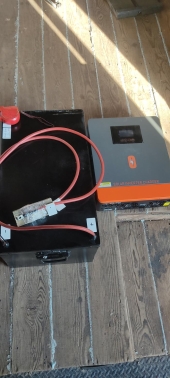
Sebastian Köln wrote:It looks to me like the connection between the wire and the fuse wasn't good (enough).


I agree with Sebastian.  I have seen this before where the wires are not securely connected to the circuit breaker's terminals.  If the connection is loose , there will be electrical resistance, and when you pass a current through that point, it will generate heat.  The amount of heat will be proportional to the load (the amount of current being drawn).

Make sure that the connections are tight.  When you have more than one wire, depending on the type of clamp used for the breaker's terminal, you may find that one wire has a tight connection and the other a bit loose. Imagine a clamp with a bolt in the centre used to push down clamp.  If you have one wire in the centre of the clamp and another off to the side, the wire directly under the bolt may be more pressure than the one on the side.  I would recommend tightly twisting the wires together and then clamping to ensure that there is good contact for all wires.
 
gardener & hugelmaster
Posts: 3750
Location: Gulf of Mexico cajun zone 8
2013
cattle hugelkultur cat dog trees hunting chicken bee woodworking homestead ungarbage
  • Mark post as helpful
  • send pies
    Number of slices to send:
    Optional 'thank-you' note:
  • Quote
  • Report post to moderator
What they said plus ...

If the rated max output spec is 16 amps why are the fuses 20? I would probably try 15 to be safer.

Hard to see from the pic but is that a push in type wire connection or a screw in type? In my opinion & experience the push in types are unreliable.

Are all the individual loads hooked up to the inverter still functioning properly? Is the inverter?

 
steward
Posts: 4837
Location: West Tennessee
2440
cattle cat purity fungi trees books chicken food preservation cooking building homestead
  • Mark post as helpful
  • send pies
    Number of slices to send:
    Optional 'thank-you' note:
  • Quote
  • Report post to moderator
I'm not a solar guy, but I understand a few things about household electricity that I'd like to share.

Theres a phenomenon that occurs when two dissimilar metals are in contact and an electrical current is present, and it will cause corrosion, which can cause resistance then heat. The wire in the picture looks shiny, do you know if it's aluminum wire or tinned copper? But it sounds like what you have is new and I don't think this is what is happening, but I think dissimilar metal corrosion is something that do-it-yourselfers such as myself ought to be aware of and keep in their back pocket, so to say, when trying to diagnose a problem. This is more common with aluminum wire, and it is good practice for bare terminated ends of aluminum wire to have de-ox compound on them to prevent this corrosion.

The only thing that sticks out in my mind from the picture is the two wire ends don't appear to have been twisted together first before being inserted into the fuse clamp. In residential and commercial wiring, codes requires pairs or more to be twisted together first before being connected with a wire nut or clamp. If not, loosening from expansion & contraction from hot & cold from varying loads and current resistance, like Ron mentioned above, can happen which may cause sparks and potentially a fire.
 
pollinator
Posts: 936
Location: Central Ontario
171
kids dog books chicken earthworks cooking solar wood heat woodworking homestead
  • Mark post as helpful
  • send pies
    Number of slices to send:
    Optional 'thank-you' note:
  • Quote
  • Report post to moderator
Hi Nuno,
It sure looks like a case of a badly fastened wire. DC current will arc continually and at approx 100 plus volts on that string quite aggressively if those wires are not properly tightened. The arcing produces heat which melts and chars the insulation and breaker.Situations like these are the exact reason that a combiner is usually used at the array or in your case two separate breakers one for each string. Some breakers are made with two separate indentations to clamp on two wires. That one is not So it would be almost impossible to make sure they were both clamped properly.  it looks like its made to clamp onto one 10 gauge homerun cable which is what would normally go to it for 32 amps... If it was me I would change the breakers to match the gauge of the wire and tie them in separately.Same for the positive side. Re reading your post it seems like you came to the same conclusion...
Cheers,  David
 
Sebastian Köln
Posts: 747
Location: Morocco
103
cat forest garden trees solar wood heat woodworking
  • Likes 1
  • Mark post as helpful
  • send pies
    Number of slices to send:
    Optional 'thank-you' note:
  • Quote
  • Report post to moderator
Or you could solder the two wires together. Solder is somewhat flexible, so it should give a good contact. Maybe even make it somewhat flat with a hammer to give contact on the whole surface.
 
pollinator
Posts: 1234
Location: Chicago/San Francisco
196
  • Likes 3
  • Mark post as helpful
  • send pies
    Number of slices to send:
    Optional 'thank-you' note:
  • Quote
  • Report post to moderator
Hard to make a good connection with more than one naked wire onto the same terminal. Even twisting them is troublesome. If more than one wire terminates on a terminal you might want to install connectors on the ends of the wires - either ring connectors (prevents the wire falling off even if the terminal is loose) or the fork connectors. Sized for the wire _and_ the connecting screw. Using crimped on connectors makes it a lot less problematic to "stack" wires on a terminal. Although, in truth, stacking connections is not generally recommended.

The connectors attach to the wires using a crimp tool. Try to afford a good ratcheting crimper with dies for the wire sizes you're going to use. About $30-40. You don't _have_ to have that good tool, but it will save your hands, your temper and your time if you do more than, say, a dozen crimps on any one job.

To just "redneck" it, you can buy a simpler non-ratcheting crimper  or even just use channel lock pliers with both hands - hard. But you're trying, I think, to NOT revisit this particular situation, so getting a tool that will let you make really good crimps every single time is probably worth the bucks.

The Coast Guard writes the rules for boat wiring and they have studied what kind of wiring practice is most likely to _not_ cause them expensive rescue operations. They have outlawed solder connections for two reasons: 1) Good solder connections is a real skill that relatively few people have. Even amoung electricians. 2) The real reason: Even with a perfect solder joint, the joint stops very abruptly where the solder ends. For a connection that is always the same temperature and never moves, in the slightest, at all, no problem. However, most connections change temperature, change size and, most critically, _move_.  Both as the result of temperature changes and from vibration, the wire flexes a little and when there is a single exact point where it bends (like where the solder ends) all the motion that might have been spread out over the 1/4" or so of that joint occurs _right there_ in the 1/64" where the solder ends. The one point is a stress riser where all the wear is concentrated and it tends to fail, fatigue and crack. They didn't figure this out right away, but their testing showed that solder joints were not as reliable as simple mechanical crimp joints. They went on to discover why. I believe the air craft industry has similar rules for the same reason. Crimp connections, properly made, work best. And it's easier to make proper crimp connections than good solder joints; faster and cleaner, too.

Regards,
Rufus
 
pollinator
Posts: 2619
Location: RRV of da Nort, USA
757
  • Mark post as helpful
  • send pies
    Number of slices to send:
    Optional 'thank-you' note:
  • Quote
  • Report post to moderator
Didn't want to create a separate thread for this topic and hope it's not inappropriate here.  

We recently had new electrical service from our cooperative installed to a new outbuilding via a private electrician.  This is overhead wire service from the cooperative's power pole to the new building to deliver 100 amp AC service.  A building that was previously in a nearby location had collapsed this past spring and the coop had quickly removed the old overhead cable and wires as a safety measure.  That cable and wires (aluminum, not copper) were simply coiled up after removal and stored over the summer with the idea that it could be used for the new building.  

Well....the new electrician wanted to use their own cable and wiring for the new install.  Soooooooo...now we are left with the previous cable (only a few years old, actually) and I'm wondering what it could be used for.  As typical for overhead service, there is a high-tensile cable around which the two power wires are wrapped as they are supported along the run from the pole to the building:  Can I just unwind the heavy-duty wires and use them for other heavy-load electrical projects?  I'm accustomed to working with copper wiring but have never worked with aluminum for routine projects.  Any reason why I should not do this and just recycle the wire instead?  Thanks!
 
pollinator
Posts: 4958
1198
transportation duck trees rabbit tiny house chicken earthworks building woodworking
  • Mark post as helpful
  • send pies
    Number of slices to send:
    Optional 'thank-you' note:
  • Quote
  • Report post to moderator

John Weiland wrote:Didn't want to create a separate thread for this topic and hope it's not inappropriate here.  

We recently had new electrical service from our cooperative installed to a new outbuilding via a private electrician.  This is overhead wire service from the cooperative's power pole to the new building to deliver 100 amp AC service.  A building that was previously in a nearby location had collapsed this past spring and the coop had quickly removed the old overhead cable and wires as a safety measure.  That cable and wires (aluminum, not copper) were simply coiled up after removal and stored over the summer with the idea that it could be used for the new building.  

Well....the new electrician wanted to use their own cable and wiring for the new install.  Soooooooo...now we are left with the previous cable (only a few years old, actually) and I'm wondering what it could be used for.  As typical for overhead service, there is a high-tensile cable around which the two power wires are wrapped as they are supported along the run from the pole to the building:  Can I just unwind the heavy-duty wires and use them for other heavy-load electrical projects?  I'm accustomed to working with copper wiring but have never worked with aluminum for routine projects.  Any reason why I should not do this and just recycle the wire instead?  Thanks!


You can use it.

There was a Home Depot that was closing near me, and so I told the woman in electrical I would give her $75 for a roll of aluminum entrance cable that was sitting on the floor. Neither one of us knew how much was taken, so she went for it, and there had to be over 400 feet on that spool. It was the best deal in wire that I ever got, so I have used that wire many times. You can always up-size wire. I just use the special grease you must use to make the contacts with the aluminum wire. I have never had an issue using it, and I still got more of it.
 
gardener
Posts: 874
Location: Piedmont 7a
324
7
hugelkultur trees woodworking
  • Mark post as helpful
  • send pies
    Number of slices to send:
    Optional 'thank-you' note:
  • Quote
  • Report post to moderator
Please take this with a grain of salt, as I am not an electrician, and I don’t play one on TV.  

From the picture, I am wondering if that is what a home inspector would call a ‘double tap’ - meaning two wires going into a breaker designed for a single wire?  They don’t like it for the very reason the picture illustrates - if the wires are loosely connected, or the breaker overloaded, it can cause a fire. Some options for fixing in this article:

https://structuretech1.com/double-tapped-circuit-breakers/
 
Anderson gave himself the promotion. So I gave myself this tiny ad:
Binge on 17 Seasons of Permaculture Design Monkeys!
http://permaculture-design-course.com
reply
    Bookmark Topic Watch Topic
  • New Topic