gift
Companion Planting Guide by World Permaculture Association
will be released to subscribers in: soon!
  • Post Reply Bookmark Topic Watch Topic
  • New Topic
permaculture forums growies critters building homesteading energy monies kitchen purity ungarbage community wilderness fiber arts art permaculture artisans regional education skip experiences global resources cider press projects digital market permies.com pie forums private forums all forums
this forum made possible by our volunteer staff, including ...
master stewards:
  • Nancy Reading
  • Carla Burke
  • r ranson
  • John F Dean
  • paul wheaton
  • Pearl Sutton
stewards:
  • Jay Angler
  • Liv Smith
  • Leigh Tate
master gardeners:
  • Christopher Weeks
  • Timothy Norton
gardeners:
  • thomas rubino
  • Jeremy VanGelder
  • Maieshe Ljin

Bell questions

 
Rocket Scientist
Posts: 1809
Location: Kaslo, BC
525
building solar woodworking rocket stoves wood heat greening the desert
  • Mark post as helpful
  • send pies
    Number of slices to send:
    Optional 'thank-you' note:
  • Quote
  • Report post to moderator
I am in the middle of redoing my bench bell and after reading the site: http://batchrocket.eu/en/building#belltheory  I have a few questions.

The Bell, how it works and why

Just under picture of barrel and bell it says....

"The inside of the bell is nothing but 'space'. It does allow the hot exhaust to enter, slow down greatly, rise to the top of the bell and give its heat to the bell, cool and then fall down to almost the floor before leaving the bell via the chimney flue. "

1) I am wondering about the words "almost to the floor". My exhaust pipe comes straight down into the bell and was wondering how close to the floor of the bell it should be? See "bell 1" picture.... the brick and shim are only there temporarily to hold up the 6 inch diameter pipe which is about 6 inches off the floor. Would adding a funnel on the end of the pipe help channel the cool gasses into the pipe easier or not worth the effort?

Second to last paragraph it says...

"...internal structures (eg, columns) can be built inside the simple brick skin that can absorb, and then release later, heat. "  

2) At what point do columns or other mass inside the bell become a drag on the gas flow (if at all)? Is there a general rule of thumb to follow or is it a calculated percentage of the volume of the bell?
See picture "bell 2". The sticks in the bell were put there to support the metal 'roof' during construction but was considering replacing them with mass columns instead.
Bell-1.JPG
[Thumbnail for Bell-1.JPG]
Open 'bell' surgery to exhaust pipe
Bell-2.JPG
[Thumbnail for Bell-2.JPG]
inside of bell
Bell-3.JPG
[Thumbnail for Bell-3.JPG]
overview of system
 
gardener
Posts: 3471
Location: Southern alps, on the French side of the french /italian border 5000ft elevation
194
  • Likes 1
  • Mark post as helpful
  • send pies
    Number of slices to send:
    Optional 'thank-you' note:
  • Quote
  • Report post to moderator
Gerry.

The "plunger tube" you are using, needs to have a gap from the floor, of at least system CSA. But, if the cooled gasses can't enter from all around at the same time, with a wall nearby or else. 2 or 3 times CSA is better.  It works the same as top gap or hear riser gap. Tho, cooled down gases are slower, denser, and if hotter than ambient,  they tend to rise naturally, creating a depression at the mouth of the plunger tube, so no need to make the gap too big. The larger the dimension between bell's top and plunger tube mouth,. The greater the temperature difference between the two. Hence better hear retaining.  A good trick i like, fit two tubes of the same diameter in each others, cutting one up, to allow insertion into the other. (rivet it's two lips so it holds by friction in the other) So you can push it up or down, to fine tune your system.

Another one, is trumpet bell end.

Imagine, a 6 inch tube's gap is 18.84 inches per inch of gap.

If you use a "trumpet bell" or funnel, let say increasing the diameter 4 inches, so you have the lip spanning 10 inches, you have then 31.41 square inches per inch of gap. So your gap can be smaller to the floor, gaining more heat retaining.
 
gardener
Posts: 1054
Location: +52° 1' 47.40", +4° 22' 57.80"
447
woodworking rocket stoves wood heat
  • Likes 2
  • Mark post as helpful
  • send pies
    Number of slices to send:
    Optional 'thank-you' note:
  • Quote
  • Report post to moderator

Gerry Parent wrote:1)I am wondering about the words "almost to the floor". My exhaust pipe comes straight down into the bell and was wondering how close to the floor of the bell it should be? See "bell 1" picture.... the brick and shim are only there temporarily to hold up the 6 inch diameter pipe which is about 6 inches off the floor. Would adding a funnel on the end of the pipe help channel the cool gasses into the pipe easier or not worth the effort?


In any bell, the exhaust gases won't stream all in a horizontal route to the exhaust opening. Due to the temperature differences most gases are coming down to the exhaust, hardly touching the floor at all. The higher the exhaust opening, the less of the bell's surface is employed to extract heat. The way you have situated the plunger pipe means one side isn't very effective in exhausting because there's a wall close by (or so it seems).

Imagine all gases come from above, then it's easy to see the circumference of the pipe is playing an important role. As Satamax remarks, there's an imaginary ring under the pipe which need to be wider than the csa of the pipe. Take the circumference of the pipe and multiply it with the distance to the floor. The resulting figure should be about two times the pipe's csa in order to allow the gases to round the 180 degrees direction change easily. In your case: 6" * PI = 18.8"² * 1.5" = 28.3"², being the csa of the 6" pipe. In order to create enough room there should be at least 3" distance between pipe end and floor. Mark, however, this is valid only when the pipe has plenty of room all around. When one side of the pipe is close to a wall you need to deduct some of the circumference and the outcome will be a larger distance from the floor. A trumpet end of the pipe (or using a reducer) should widen the diameter so the distance to the floor could be reduced, allowing more of the surface of the bell to extract heat, provided it's free all around of course.
Hmm... the above looks a bit complicated, I hope it is clear anyway.

Gerry Parent wrote:1)2) At what point do columns or other mass inside the bell become a drag on the gas flow (if at all)? Is there a general rule of thumb to follow or is it a calculated percentage of the volume of the bell?


Good question! The workings of a bell relies on the difference in volume between the exhaust (and inlet) pipe and the bell. To see what the difference is, take a cross section area of the bell/bench where a column is and compare it to the csa of the exhaust. The resulting figure should be at least 5 times the pipe's csa, preferably more. In other words: the smaller the bell, the less the gases are able to slow down and stratify, separating the hotter form the colder gases. One column every 4 feet won't affect the bell's aerodynamics much, but every 1 foot does.
 
Gerry Parent
Rocket Scientist
Posts: 1809
Location: Kaslo, BC
525
building solar woodworking rocket stoves wood heat greening the desert
  • Mark post as helpful
  • send pies
    Number of slices to send:
    Optional 'thank-you' note:
  • Quote
  • Report post to moderator

The "plunger tube" you are using, needs to have a gap from the floor, of at least system CSA. But, if the cooled gasses can't enter from all around at the same time, with a wall nearby or else. 2 or 3 times CSA is better.


Satamax,

So if the system CSA is 28.26 and each inch of gap is 18.84 then the gap would need to be at least (28.26 divided by 18.84) = 1.5 inches...... but because the exhaust tube is close to a wall, the gap should be more like 1.5 x 3 (times system size) = 4.5 inches. However as you suggested, it makes more sense to put a  "trumpet bell" or funnel to reduce this gap. So if the end of the funnel was now 9 inches in diameter at 28.27 CSA the gap would only need to be 1 inch.....and again making it 3x bigger because of the wall would = 3 inches.

It works the same as top gap or hear riser gap. Tho, cooled down gases are slower, denser, and if hotter than ambient,  they tend to rise naturally, creating a depression at the mouth of the plunger tube, so no need to make the gap too big.


I'm not sure what you mean by creating a depression? I imagining the gases wearing away a little crater just below the opening of the exhaust tube on the floor of the bell. I'm pretty sure this is not what you mean and wondering if you could elaborate a bit further please.


A good trick i like, fit two tubes of the same diameter in each others, cutting one up, to allow insertion into the other. (rivet it's two lips so it holds by friction in the other) So you can push it up or down, to fine tune your system.  


I had a flash of your idea of fine tuning the gap with an adjustable pipe just after I pushed the "submit" button but dismissed it because I didn't know how to get back to it once everything was all covered up again. Reaching in where my closest cleanout is would be tricky at best to make adjustments but not impossible..... unless the overlap was just above the top of the bench where it could be accessed easier on the fly while the fire is still burning and giving me more instant results of its new position and its effects on performance. I would imagine this is just a temporary trick until you find the sweet spot then leave it where it is correct?

Peter, I'll respond to your post soon. Thanks


Gerry Parent
Rocket Scientist
Posts: 1809
Location: Kaslo, BC
525
building solar woodworking rocket stoves wood heat greening the desert
  • Mark post as helpful
  • send pies
    Number of slices to send:
    Optional 'thank-you' note:
  • Quote
  • Report post to moderator

The way you have situated the plunger pipe means one side isn't very effective in exhausting because there's a wall close by (or so it seems).


Peter,
This is true, the backside of the exhaust pipe is touching the wall of the bell to make as much room in the front side for the incoming hot air from the manifold to make its way into the bell. Of course in my pictures, these extra walls haven't yet been made yet until I settled on my previous inquiries. In fact, I was also strongly considering adding a bypass from my older pipe bench system (see picture "bypass midway") in this space as last year on the shoulder season I had a major backflow of smoke billowing out the feed tube that I couldn't reverse and was forced to douse it with water to make it stop. Obviously the bell was robbing way too much heat from the exhaust and couldn't get the thermosiphon started. The problem I am now seeing with this idea though is what you and Satamax have been saying about not being effective in exhausting because of the close proximity of the walls. Once the bypass pipes and separator wall go in, only one small side would be left to access the hole for the exhaust tube leaving the gap from the bottom of the tube to the floor way too high to be very efficient.
I am not married to the idea of needing a bypass and all its complexities but I had grown to like its quick and easy way of priming the system without resorting to fans or wads of burning paper shoved into a priming hole.   Any other ideas?

One quick thought...has the idea of Satamaxs' sliding pipe trick ever been tried more extremely as a bypass alternative? You know, where the end of the exhaust pipe would slide all the way to the top of the bell allowing the hot gases to escape the bell quickly, then once primed, lowering it to a preset distance from the bottom to do its stratification thing?

The picture "arch completed" was my former bell inlet (right) and exhaust (left) ports. The exhaust was a 6 " diameter pipe with a 90 degree elbow at the bottom and the inlet was around 7" in diameter.  It worked fairly well but again wanted to experiment further which brings me to where I am now.

As for adding columns, I feel like there's enough on my plate right now but will consider it in a future incarnation.

bypass-midway.JPG
[Thumbnail for bypass-midway.JPG]
arch-completed.JPG
[Thumbnail for arch-completed.JPG]
 
Satamax Antone
gardener
Posts: 3471
Location: Southern alps, on the French side of the french /italian border 5000ft elevation
194
  • Mark post as helpful
  • send pies
    Number of slices to send:
    Optional 'thank-you' note:
  • Quote
  • Report post to moderator

I'm not sure what you mean by creating a depression? I imagining the gases wearing away a little crater just below the opening of the exhaust tube on the floor of the bell. I'm pretty sure this is not what you mean and wondering if you could elaborate a bit further please.


Gerry, do you know what is a venturi?

Basically how it works  in a plunger tube. You have gases around, which have not stalled, but are rather lazy, and then these enter a tube, leading to the great outsides. These are hotter, hence lighter than outside air. So they rush up (well, are pushed up by the outside pressure  reflected on all the gases inside. Gases get hot, and lighter, they are pushed up by denser colder air)

But once they are in a column of air, they behave rather nicely.

Tho, this is not the case at the mouth of the plunger tube. First they need to change  direction. Their main lazy movement is mostly horizontal. Change of direction creates turbulence, and turbulence, friction, they resist the drag. So this first effect creates a slight depression at the mouth of the plunger tube. Then, there's also the gases sucked down from outside the tube, a smidge further up. May be half inch or so. These go down, then at 90° towards the center of the tube, until they change direction again taken by the vertical flow. since those resist going up too, this creates a slight vacuum at the mouth of the tube. Then the friction stated earlier has another effect, it increases the boundary layer, which then behaves a bit better further up the tube, it's a matter of one inch or two, usually, it makes a kind of cushion of gas, shaped like a plane wing or teardrop. Forming a ghost venturi (well, depending on turbulences, it's shape varies) and the vacuum forms the most at the back of this ghost venturi. We're talking micro-grams of pressure difference. But it exists.

https://en.wikipedia.org/wiki/Venturi_effect

https://en.wikipedia.org/wiki/Stack_effect


Gerry Parent
Rocket Scientist
Posts: 1809
Location: Kaslo, BC
525
building solar woodworking rocket stoves wood heat greening the desert
  • Mark post as helpful
  • send pies
    Number of slices to send:
    Optional 'thank-you' note:
  • Quote
  • Report post to moderator
Thank you for the explanation Satamax. Its going to take me a bit of reading to grasp the forces at work and how they behave. One thing I can say for sure though is that there is so much more to the dynamics of burning and exhausting flue gases than meets the eye. I appreciate your patience with this.

One extra question: Does the drop tube need to be insulated or can it be just left bare?

 
Satamax Antone
gardener
Posts: 3471
Location: Southern alps, on the French side of the french /italian border 5000ft elevation
194
  • Mark post as helpful
  • send pies
    Number of slices to send:
    Optional 'thank-you' note:
  • Quote
  • Report post to moderator

Gerry Parent wrote:
One extra question: Does the drop tube need to be insulated or can it be just left bare?


It depends!

If you're into trying to extract every last BTU left in the hot gases, or if you have a slightly misbehaving heater, with a bell on the large side.

If the former, you insulate, so you don't lose energy to reheat already cooled gases. As long as they are hotter than ambient, and sufficient to keep themselves moving fast enough for the heater. Fine.

If the later, you might find beneficial to reheat the gases flowing through the plunger tube, so they move a bit faster and your stove doesn't stall.
 
Gerry Parent
Rocket Scientist
Posts: 1809
Location: Kaslo, BC
525
building solar woodworking rocket stoves wood heat greening the desert
  • Mark post as helpful
  • send pies
    Number of slices to send:
    Optional 'thank-you' note:
  • Quote
  • Report post to moderator
OK Satamax, I drew up a picture of what I could extract from your description of the "Ghost Venturi". Could you comment on its accuracy (or lack of) so I can visually see why things behave the way they do.

Also, perusing through the http://energy.concord.org/energy2d/models.html website, I couldn't find anything related that might show a moving and interactive picture of what I crudely am trying to see.
Ghost-Venturi2.JPG
[Thumbnail for Ghost-Venturi2.JPG]
 
Satamax Antone
gardener
Posts: 3471
Location: Southern alps, on the French side of the french /italian border 5000ft elevation
194
  • Mark post as helpful
  • send pies
    Number of slices to send:
    Optional 'thank-you' note:
  • Quote
  • Report post to moderator
Gerry, in a straight tube, i understand what happens. In a tube with a funnel. I have to think.

See at 0.51, The standing fluid after the funnel. Pretty much of what happens after the entrance of a tube, when the fluid can come from all directions. Tho, far less than this.


At 5..03, you can see the effect of the boundary layer. Imagine the two sides  being curved, you have a sort of funnel. Gases in the middle travel faster.

But you know, this is trivial for anything above 3 or 4 inches. The boundary layer affecting one inch each side, from 0 against the wall, to full speed 3 cm (ok, bit more than an inch) further away.

At 7.46 again, you have interesting images. On the convex part, you can see the cushion which forms.

14.30 again, straight tube, to widening tube. Then after, inverted funnel. With a  nice standing wave.

 
Gerry Parent
Rocket Scientist
Posts: 1809
Location: Kaslo, BC
525
building solar woodworking rocket stoves wood heat greening the desert
  • Mark post as helpful
  • send pies
    Number of slices to send:
    Optional 'thank-you' note:
  • Quote
  • Report post to moderator
Thanks for the video. The visualization was helpful even though in the real world each imperfection or jutting piece of cob could cause a whole new phenomena to occur. Trial and error along with patience and observation will teach me which is kind of fun too.
Getting back to more basics, I am starting to put things back together and was wondering if there was an optimal height off the floor at which the hot air entering the bell should be at? Any reason why it can't be at the very top or would this cause too much disturbance to the gases already in the bell trying to stratify?

 
Satamax Antone
gardener
Posts: 3471
Location: Southern alps, on the French side of the french /italian border 5000ft elevation
194
  • Mark post as helpful
  • send pies
    Number of slices to send:
    Optional 'thank-you' note:
  • Quote
  • Report post to moderator
Entering the top of the bell, messes with the stratification. Tho, in a single bell, this is what happens anyway!
 
Gerry Parent
Rocket Scientist
Posts: 1809
Location: Kaslo, BC
525
building solar woodworking rocket stoves wood heat greening the desert
  • Mark post as helpful
  • send pies
    Number of slices to send:
    Optional 'thank-you' note:
  • Quote
  • Report post to moderator
So what your saying is there is no optimal height for it to be so just plunk it somewhere lets say between half way and the top and experiment to give the best results for each particular system?

Another question..... Does it matter the shape? For instance, as we're interested in stratification (and not trying to disturb it as much as possible), would it be better to make a more oval or even horizontal rectangle as the opening as long as it maintains system CSA?
 
Gerry Parent
Rocket Scientist
Posts: 1809
Location: Kaslo, BC
525
building solar woodworking rocket stoves wood heat greening the desert
  • Mark post as helpful
  • send pies
    Number of slices to send:
    Optional 'thank-you' note:
  • Quote
  • Report post to moderator
OK, so to contradict what I just said, after reading article on free gas movement  http://www.stove.ru/index.php?lng=1&rs=16  it says....

"8. Heat energy source can be located in any place within the lower zone of the bell. Regardless of the location of the source, character of the heating process remains the same."

So even though in my bell bench having the proximity of the the input and output pretty much right next to each other ( approx 3 inches - due to the limited space I'm working with) it doesn't really seem to matter as the "character of the heating process remains the same"

I think I remember reading somewhere on permies a while back that a divider wall between the input and output isn't necessary as the gases won't shortcut but rather follow their nature...hot air rising while cold air sinking.
 
Satamax Antone
gardener
Posts: 3471
Location: Southern alps, on the French side of the french /italian border 5000ft elevation
194
  • Likes 1
  • Mark post as helpful
  • send pies
    Number of slices to send:
    Optional 'thank-you' note:
  • Quote
  • Report post to moderator

Gerry Parent wrote:So what your saying is there is no optimal height for it to be so just plunk it somewhere lets say between half way and the top and experiment to give the best results for each particular system?

Another question..... Does it matter the shape? For instance, as we're interested in stratification (and not trying to disturb it as much as possible), would it be better to make a more oval or even horizontal rectangle as the opening as long as it maintains system CSA?


Well, what i'm saying, is that we know the best bell design. Low entrance, low exit, tall, with enough internal surface area, and enough mass. Tho, the later two are tricky. Too much ISA, and you get stalling, too much mass, and your stove doesn't heat. Releasing more heat to the air flowing in it, after the fire has died; more than the heat has time to travel through the thick mass walls.


The shape of entrance, and exit are better shallow and wide. Tho, remember, anything less than 2.5 inch in height, you will have to widen more than CSA, to counteract the effect of the boundary layer.  Furthermore, even before this limit, you have to care for the fact that gases travel slower at the very floor level. That they have to turn two edges to enter the chimney. So Peter says 2 to 3 times CSA is better.

One side note. The shape of the bell can be important too.

Lets say, a round bell has the least iSA for it's internal volume. And so less mass. A square bell has more ISA, and can have more mass, if the walls thickness is the same as the round one. And a star shaped bell, has even more ISA. And can have even more mass.

About the Kutznetov quote.

Well, i'd tame his words.

If entrance and exit are real close, a little stub wall between the two could be in order, to shape the flow of gases. And avoid bypass.
 
Gerry Parent
Rocket Scientist
Posts: 1809
Location: Kaslo, BC
525
building solar woodworking rocket stoves wood heat greening the desert
  • Mark post as helpful
  • send pies
    Number of slices to send:
    Optional 'thank-you' note:
  • Quote
  • Report post to moderator

The shape of entrance, and exit are better shallow and wide. Tho, remember, anything less than 2.5 inch in height, you will have to widen more than CSA, to counteract the effect of the boundary layer.  Furthermore, even before this limit, you have to care for the fact that gases travel slower at the very floor level. That they have to turn two edges to enter the chimney. So Peter says 2 to 3 times CSA is better.


So your saying that the plunger tube is not as effective as a shallow and wide approach?  So it would be even better (efficient) if I add on a 90 degree pipe to the end of my plunger tube then rework the end with cob or add a metal heat register boot end onto it (assuming the opening is big enough) and keeping in mind the rest of what you said?

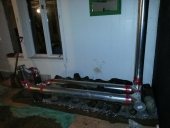
See picture of my current setup before I modify it - note the cone or trumpet on the end of the plunger tube is not completely around as this was just a scrap piece I had kicking around and wasn't long enough. Also, the bottom edge of the cone is about 4 inches up from the floor and is about level with the bottom opening of the exhaust inlet (which may also need to be modified to be shallow and wide).

One side note. The shape of the bell can be important too.


Very useful information to know for my next build but due to the restrictions of my shop I can't fiddle with the bell shape at all, only the entrance and exit.
Plunger-tube-with-cone2.JPG
[Thumbnail for Plunger-tube-with-cone2.JPG]
 
Posts: 18
Location: Colorado Frontrange
1
  • Mark post as helpful
  • send pies
    Number of slices to send:
    Optional 'thank-you' note:
  • Quote
  • Report post to moderator

Satamax Antone wrote:
Well, what i'm saying, is that we know the best bell design. Low entrance, low exit, tall, with enough internal surface area, and enough mass.


I'm surprised by the recommendation to have a low entrance. If stratification of the gases in the bell is the objective, then the entrance should be high (and lowest velocity possible) to minimize mixing of the stratification layers. Is there some other reason to locate the entrance low?
 
Satamax Antone
gardener
Posts: 3471
Location: Southern alps, on the French side of the french /italian border 5000ft elevation
194
  • Mark post as helpful
  • send pies
    Number of slices to send:
    Optional 'thank-you' note:
  • Quote
  • Report post to moderator
Gerry, plunger tube is another story. Since it's metal, it heats up, and in turn reheating the gases which travel through it, giving a suction effect. And in the case of a plunger tube, wide and shallow, translates in bigger diameter you can practically  fit, or make it a bell end. To have a better ring projection. http://donkey32.proboards.com/thread/1406/calculating-ring-circumference-projection-gap  

Jason Durrie wrote:

Satamax Antone wrote:
Well, what i'm saying, is that we know the best bell design. Low entrance, low exit, tall, with enough internal surface area, and enough mass.


I'm surprised by the recommendation to have a low entrance. If stratification of the gases in the bell is the objective, then the entrance should be high (and lowest velocity possible) to minimize mixing of the stratification layers. Is there some other reason to locate the entrance low?


High entrance messes with stratification. And it's not a bell anymore, but a downdraft channel, of a huge size. When it is a single bell, with the rocket incorporated, no choice. But otherwise, it's better to have low entrance, and low exit, because the pressures equate. Downdraft is detracting from the natural draft.

https://en.wikipedia.org/wiki/Stack_effect

http://www.stove.ru/index.php?lng=1&rs=16
 
Gerry Parent
Rocket Scientist
Posts: 1809
Location: Kaslo, BC
525
building solar woodworking rocket stoves wood heat greening the desert
  • Mark post as helpful
  • send pies
    Number of slices to send:
    Optional 'thank-you' note:
  • Quote
  • Report post to moderator
So this is where I am now. I waited until it 'cooled off' to 75F last night but because it was the same temperature inside as it was outside, I wasn't optimistic. Sure enough, in little over 5 minutes of burning, it started to puff back and a few minutes later almost flowing in the reverse direction forcing me to remove the wood and inhale some of my first (and hopefully last) smoke of the season. I take this as what happens when there is not enough temperature differential to keep the stack effect going rather than a design flaw somewhere. I could add a bypass (which I almost did) but just wanted to keep it simple - besides, its not meant to heat the shop in the summer! It was mostly my impatience to see how it would behave in a worse case scenario.  I won't really know until we get a chilly night to do a fair test (which could be another month) before I decide to trim down on efficiency prematurely.
plunger-tube-4-inches-from-floor.JPG
[Thumbnail for plunger-tube-4-inches-from-floor.JPG]
All-covered-up-with-cob.JPG
[Thumbnail for All-covered-up-with-cob.JPG]
 
Gerry Parent
Rocket Scientist
Posts: 1809
Location: Kaslo, BC
525
building solar woodworking rocket stoves wood heat greening the desert
  • Mark post as helpful
  • send pies
    Number of slices to send:
    Optional 'thank-you' note:
  • Quote
  • Report post to moderator

Gerry, plunger tube is another story. Since it's metal, it heats up, and in turn reheating the gases which travel through it, giving a suction effect.  


and...

If the former, you insulate, so you don't lose energy to reheat already cooled gases. As long as they are hotter than ambient, and sufficient to keep themselves moving fast enough for the heater. Fine.  


Update - The temperature outside went down to 45F and I tried lighting it again - this time with no smoke coming out the feed tube and a fairly good draw. However, I have a probe thermometer inserted in the exhaust pipe about head level that reads the temperature in center of the exhaust stream and it went up to 350F in in about 20minutes.... way too high for my liking so its back to opening it up again and putting some insulation around the plunger tube inside the bell to get the exit temperatures down.
 
Satamax Antone
gardener
Posts: 3471
Location: Southern alps, on the French side of the french /italian border 5000ft elevation
194
  • Mark post as helpful
  • send pies
    Number of slices to send:
    Optional 'thank-you' note:
  • Quote
  • Report post to moderator

Satamax Antone wrote:Gerry, plunger tube is another story. Since it's metal, it heats up, and in turn reheating the gases which travel through it,


I told ya didn't i?
 
Gerry Parent
Rocket Scientist
Posts: 1809
Location: Kaslo, BC
525
building solar woodworking rocket stoves wood heat greening the desert
  • Mark post as helpful
  • send pies
    Number of slices to send:
    Optional 'thank-you' note:
  • Quote
  • Report post to moderator
OK   'Mr. Cheeky'  it was what you said but nothing like good ole first hand experience to see which way the cookie would crumble.
 
Gerry Parent
Rocket Scientist
Posts: 1809
Location: Kaslo, BC
525
building solar woodworking rocket stoves wood heat greening the desert
  • Mark post as helpful
  • send pies
    Number of slices to send:
    Optional 'thank-you' note:
  • Quote
  • Report post to moderator
Update:  Adding about 3 inches of rock wool around the plunger tube and cobbing it in did the trick.
It now produces an exhaust around 125 - 150 F.
Long term burns are still needed but happy to know its ready to go again.
insulated-tube-in-place-ready-for-cob.JPG
[Thumbnail for insulated-tube-in-place-ready-for-cob.JPG]
insulated-tube-cobbed-and-ready-to-be-tested.JPG
[Thumbnail for insulated-tube-cobbed-and-ready-to-be-tested.JPG]
 
Posts: 20
5
5
  • Mark post as helpful
  • send pies
    Number of slices to send:
    Optional 'thank-you' note:
  • Quote
  • Report post to moderator

Peter van den Berg wrote:
Good question! The workings of a bell relies on the difference in volume between the exhaust (and inlet) pipe and the bell. To see what the difference is, take a cross section area of the bell/bench where a column is and compare it to the csa of the exhaust. The resulting figure should be at least 5 times the pipe's csa, preferably more. In other words: the smaller the bell, the less the gases are able to slow down and stratify, separating the hotter form the colder gases. One column every 4 feet won't affect the bell's aerodynamics much, but every 1 foot does.


Peter,
I am building an 8" batch box. I am planning the bell to have a dead-end bench, similar to the one on your web site.
Does what you say above apply to heat/gases flowing into the bench?
The CSA of the bench will be 160 in2, which is only 3+ times the exhaust (and inlet) CSA. Is this a problem? Do I need to enlarge the CSA of the bench for it to perform properly?
 
Peter van den Berg
gardener
Posts: 1054
Location: +52° 1' 47.40", +4° 22' 57.80"
447
woodworking rocket stoves wood heat
  • Likes 1
  • Mark post as helpful
  • send pies
    Number of slices to send:
    Optional 'thank-you' note:
  • Quote
  • Report post to moderator
A dead end bench of that size would work, provided it is constructed as shown on the website. The bench isn't a second bell in this case, but an extension of the main bell instead. By the way, the heater of the MHA workshop did sport benches only 3.5 times the riser's csa and did function flawlessly nevertheless.

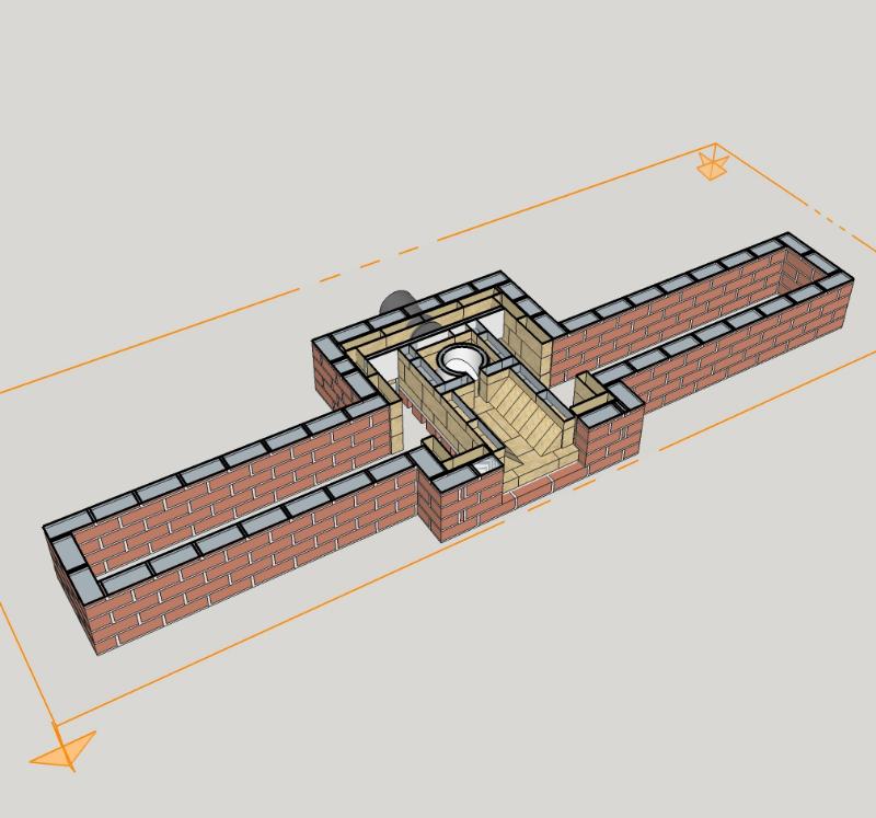
Here's a section plane of that heater which clearly shows the total csa of bell and benches together.

 
Kelly Pridgen
Posts: 20
5
5
  • Mark post as helpful
  • send pies
    Number of slices to send:
    Optional 'thank-you' note:
  • Quote
  • Report post to moderator

Peter van den Berg wrote:A dead end bench of that size would work, provided it is constructed as shown on the website.


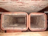
I like the concept of using a plunger tube made with brick in one corner of the bell. The key would be in making the opening as low to the floor as possible in order for the dead-end bench (I'm only making one) to function properly.
I believe this would negate the need for the baffle board.
Is my thinking correct?
 
Peter van den Berg
gardener
Posts: 1054
Location: +52° 1' 47.40", +4° 22' 57.80"
447
woodworking rocket stoves wood heat
  • Mark post as helpful
  • send pies
    Number of slices to send:
    Optional 'thank-you' note:
  • Quote
  • Report post to moderator

Kelly Pridgen wrote:I like the concept of using a plunger tube made with brick in one corner of the bell. The key would be in making the opening as low to the floor as possible in order for the dead-end bench (I'm only making one) to function properly. I believe this would negate the need for the baffle board. Is my thinking correct?


Yes, that's true.
 
Kelly Pridgen
Posts: 20
5
5
  • Mark post as helpful
  • send pies
    Number of slices to send:
    Optional 'thank-you' note:
  • Quote
  • Report post to moderator
Thanks, Peter.
A couple more questions on using a plunger tube made of brick inside the bell.
1. Does the external surface area of the brick plunger tube count towards the total ISA of the bell?

2. I'd prefer to keep it simple with a 8" square plunger tube (for 8" batchbox). Hope square is ok. I understand the factors that make a round (or octagon) shape better in the riser, but do they apply for the plunger tube?
 
Satamax Antone
gardener
Posts: 3471
Location: Southern alps, on the French side of the french /italian border 5000ft elevation
194
  • Mark post as helpful
  • send pies
    Number of slices to send:
    Optional 'thank-you' note:
  • Quote
  • Report post to moderator

Kelly Pridgen wrote:Thanks, Peter.
A couple more questions on using a plunger tube made of brick inside the bell.
1. Does the external surface area of the brick plunger tube count towards the total ISA of the bell?


I would say yes. But as the plunger tube has hot gases in and out, it doesn't extract much heat. So, from a cold start, it's definitely a part of the bell's ISA. But when hot may be not as much.

Kelly Pridgen wrote:2. I'd prefer to keep it simple with a 8" square plunger tube (for 8" batchbox). Hope square is ok. I understand the factors that make a round (or octagon) shape better in the riser, but do they apply for the plunger tube?

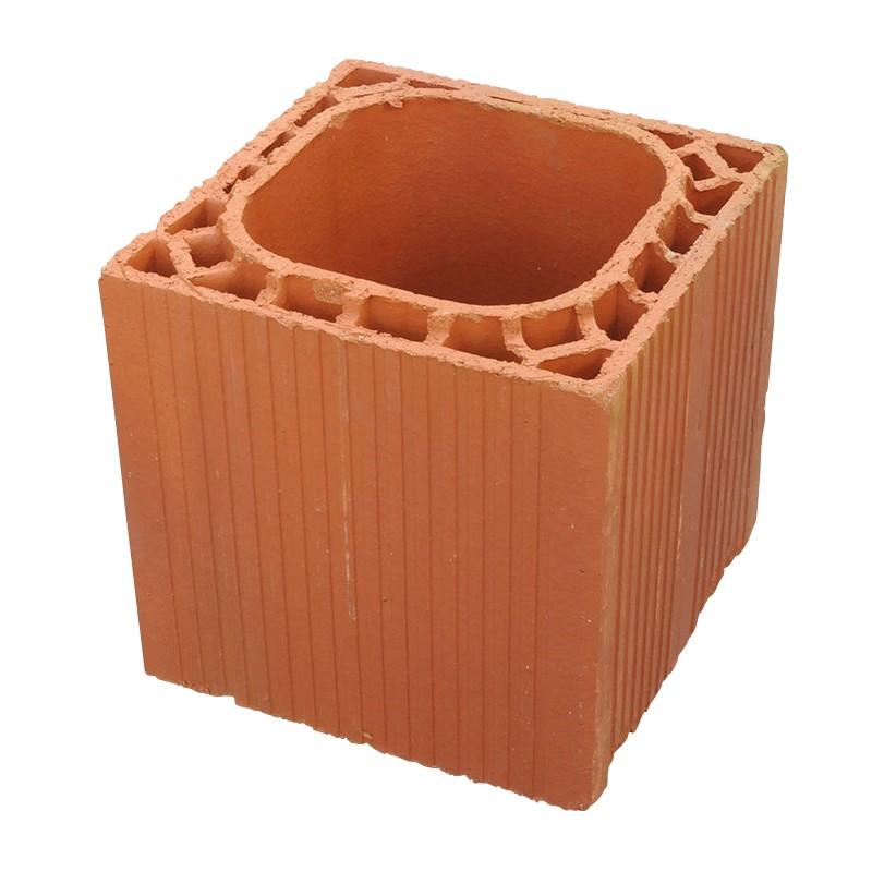

8 square is all right. I use this for chimneys.


Pozolan chimney elements.

In France we use this too


Very common in all south and eastern parts of Europe.

Not real square, not real round either!  
 
Peter van den Berg
gardener
Posts: 1054
Location: +52° 1' 47.40", +4° 22' 57.80"
447
woodworking rocket stoves wood heat
  • Mark post as helpful
  • send pies
    Number of slices to send:
    Optional 'thank-you' note:
  • Quote
  • Report post to moderator

Kelly Pridgen wrote:1. Does the external surface area of the brick plunger tube count towards the total ISA of the bell?


When built out of brick, yes. Especially in the case the bricks aren't used on edge but flat instead. So built into a corner the total of ISA doesn't change. Admittendly, the inside of the plunger tube (or upstream channel) will warm up eventually, although the coolest gases are passing there so it's always lagging behind.

Kelly Pridgen wrote:2. I'd prefer to keep it simple with a 8" square plunger tube (for 8" batchbox). Hope square is ok. I understand the factors that make a round (or octagon) shape better in the riser, but do they apply for the plunger tube?


An upstream channel from the lowest point in the bell isn't the same as a riser, definitely. Square 8" chimney is OK, in practise it is on a par with a round channel of 8" diameter capacity-wise. The gases are slower in the corners due to the fact they form more or less a round and fast streaming core, gradually getting slower and cooler closer to the walls. So corners give more friction, compensating for the larger csa.
 
Well behaved women rarely make history - Eleanor Roosevelt. tiny ad:
the permaculture bootcamp in winter (plus half-assed holidays)
https://permies.com/t/149839/permaculture-projects/permaculture-bootcamp-winter-assed-holidays
reply
    Bookmark Topic Watch Topic
  • New Topic