Burton Rosenberger

pioneer
+ Follow
since Aug 30, 2013
Merit badge: bb list bbv list
For More
North Country New Hampshire
Apples and Likes
Apples
Total received
In last 30 days
0
Forums and Threads

Recent posts by Burton Rosenberger

UPDATE:

Its been a while, but we did find someone who was living in a poorly designed double envelope home (aka not modern with concerns addressed) ...

I spent a good week tweaking the WUFI models to see if we could reproduce the 2 years of data we were provided. I modeled their home and then would modify the assemblies and settings till I got what matched reality. In short, WUFI isn't capable of modeling these homes. The only thing I could do to make the numbers match up was to switch to a single envelop and make the walls R90 ... this on a building with exterior R19 walls. There were many methods I tried to model it correctly but nothing worked in away where I would be confident in "selling" the results if you will.

So we took our structure, modeled it in wufi, and ran it through as a single envelope home ... came out with equivalent 2.5 coords of wood a year required to do DHW + heating. So while we are leaving space in our floor plan for a future double envelope if required we are going to go forward with a hybrid design. We did install two massive earth tubes on either side of the building along with two internal tubes (TBZ tubes) to connect them in place of a crawlspace.

In version 1, (see attachment) on the west side of the building, the earth tubes will come into the sun room and the sun room will be used for the replacement air for the home. The sunroom here is smaller than the other side of the building. I believe it was like 22x8 and will also act as an airlock into the main part of the home. On the east side the sun room is much bigger. Its an odd shape though ... 33x30 with a garage cut out of that space at 17x20. It will be a sun room as well and also hold a sonnenhaus style drain back tank to act as a thermal mass for our recycled evacuated solar tubes with wood stove backup ... it will be used for DHW and HRH ... but I suspect with the HRH we will likely be running it in a closed loop given all the sun coming into the space.

This is going to be a multi unit place so it should be interesting to see how it works out. At the end of 2021 we had the site leveled, tubes in, all underground conduit in, FPSF* modified commercial scaled footers for the steel building in, and the ICF wall placed on top said footers. Later this year we are going to do the slab and start erecting the building if we can.  

2 years ago
Looking for someone who lives in a double envelope home. I am trying to thermally model such a home so I know what method is required to reflect reality.

We are constructing such a home next year and we are looking to figure out how much insulation will be required where, how much ventilation is required, overhang required, etc ... Lots of stuff go into one of these homes for sure.

Currently using WUFI Passive and THERM for the bulk of estimations, not looking for certification but rather just a way to accurately model choices we make to our  model. But without an actual house to compare it to it will likely be hard to model accurately.

4 years ago

Brian Cady wrote:
So Emlid M+ = server, Hotspot = caster, cellphone = rover, all connected by Wifi, using NTRIP.


M+ is the rover, it is connected to your phones hot spot, the M+ is also configured to get NTRIP connections. The NTRIP sends corrections from CORS stations which act as the Base in this case.

You walk around with a survey pole with your M+ attached. When you get to a point you want to capture you stop, get the survey pole level, then collect the data point with the Emlid app.
4 years ago
Brian I went back and edited my post a little to add links and fix the spelling mistake you found ;)

The M+ and RS+ are both single band devices and cannot talk with the M2 / RS2 devices which are multi-band if I recall correctly (you might be able to disable the multi-band of the M2/RS2 to only use GPS but it would defeat the point of having it).

NTRIP is used with a single device to get your known point using local CORS station data but has a max range of 30km for the M+/RS+ and 100km for the M2/RS2 ... the further you are away the longer it might be to get a "fixed" solution ... and if in the woods it could be harder ... both will give you cm accuracy (max 7mm for the M2 / RS2 series ... NTRIP might not be free though.

I think my setup cost ~$1430 ... (1190 for both M2's with antenna's, ~240 for the LORA modules to match).

Emlid M2 as base + NTRIP over cellular hot spot will give you the location of the M2 in real time with ~7mm accuracy.
4 years ago

Brian Cady wrote:
Burton, I'm interested in how those Emlid M2's have worked out. Have you been able to use RTK correction from them via wifi in a cell phone, or do you use one Emlid M2 as rover and one as base?
Brian
-


If by cell phone wifi you mean NTRIP corrections I have not. My phone, and my wifes phone, cannot act as a hot spot but I am not sure it would work as well as the method I am using now where I use one as a base and one as a rover. The two of them plus the LORA radios combined was still less than the cost of a complete RS2 unit and it is pretty easy to make an enclosure for the M2's using PVC.

To establish my own "known point" on the property I found a spot which was visible to most of the property and setup the base station letting it run for a good 8 hours. I then collected this data and downloaded the local CORS ( https://geodesy.noaa.gov/CORS/data.shtml ) station data for the same time frame 17 miles away. Using RTKCONV I processed the Base station data then used RTKPOST with the CORS  station set as the Base and the "Base station" set as the Rover.

This produced several charts and graphs which told me my location for the "known point" within 3 cm square (about 1 inch). I copied the location provided and now when I "setup" over the "known point" I manually enter this as the location of the base station. So long as I have line of site to the base station from the rover I always have a "fixed" solution. If I don't then sometimes I have to wait a minute or two to get my location.

Just for fun I did try to upload my data to OPUS ( https://geodesy.noaa.gov/OPUS/ ) , the new method using the gravity based geoid, to compare but it was rejected every time. OPUS only accepts L1/L2 right now ... which is kind of odd given the accuracy of those are subpar compared to L3-L5 satellites. I think the accuracy I get with the Emlid M2's was worth the cost for sure.

GENERAL UPDATE:
My mapping rig for ODM (open drone map) somehow developed an unknown issue where it would no longer process a full set of data ... even previous dataset would fail at a specific point in the process. I have been trying to reconstruct it and document it this time so I can get processing again as I have a dataset from two weeks ago ready to go and it is over 1500 pictures :D

If there is interest I can post my whole process here.

Edited:
added links to some odd acronyms used above.
4 years ago
My wife and I are in the process of designing our passive solar house and being a tech guy I have been seeking solutions to be able to do energy audits and more specifically thermal modeling. I am not an architect but know a bit about passive solar design.

We are debating getting autodesk's revit product to do our plans so we can use it, or a plugin with it, to generate a thermal model as a proof of concept before we even start work.

Are there any architects or engineers who could recommend a product which might meet our needs? It would be really cool to "model" a lot of "alternative" structures using applications like this as well.
4 years ago
Updates:
I have since flown 4 drone missions using my phantom 4 pro v2.0 at 150-160ft elevation from the takeoff point with a 70% overlapping pattern on several different occasions while at the property. This effectively provided for a 63% overlap in images with about a .5in/pixel resolution before the photos are processed. I have been using pix4dcapture on a samsung s4 tablet for the missions and given the size of the property I had to split the property in half to ensure the battery didn't run out. These images are then post processed using open drone map (ODM) where they are stitched together into one large image where each pixel is equal to 1 inch. This is then imported into my QGIS project for the property to view it as opening it with an image viewer would either crash the viewer or refuse to open because of size constraints.

The above missions were done without ground control points (GCPs) as I did not have the means to do them accurately enough where they would make a difference. This means the images are all "off" from one another and from reality but they are "close enough" to use for planning purposes.

Since these missions however I have acquired a set of Emlid M2's with LORA antennas and have started to use it with my planning process as the accuracy it provides between the base unit and the rover is 1mm over a km, and the base unit is accurate within a 3 cm square on my property in coordinate space. This is really a different topic as to how I did this but simply put I can now create GCPs and this means I can re-run the previous imagery using the new GCPs which would make them all line up with each other ... this assuming I use visible features (like rocks or stumps)

So this is where I am at right now ... I have not created any DEM models from the drone footage as they would all be "off" from reality and I was waiting to get some GCPs in place before taking the effort to convert the LAZ output from the ODM into something I could then generate a contour / hydrology / slope map from. If all goes well I plan on capturing GCPs this weekend and running another drone mission to capture changes since the last time I flew one about 3 weeks ago.

I have included four areas of interest showing the changes over time from the previous missions.
4 years ago
Sorry S Bengi it seems I didn't communicate properly or I am simply not understanding your response. I will try again.

My interest in making this post was procedures to install a dam on bedrock / ledge since normally the keyway would be "keyed" into existing soil and not resting on bedrock.

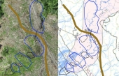
I have attached two rough concept ideas on top of an orthophoto I created along side a soil type / contour / hydrologic map I also created to give some context. The pink area in this image likely has soil depths to 15 ft where as the white is about 2ft. For scale the access road shown is 15 ft in width and each contour line is a 5ft drop in elevation

Details better explained.
We have water running year round in this area of the property.
The soil where water has historically ran is at least 15ft deep before hitting something sold.
Therefor the area were we have water will be 15ft deep or greater.
The area outside this is about 2ft to ledge.
I have not dug any test pits to confirm the depth of the soil in the desired location of the pond.

The length of the dam if done as single contour is about 300 ft. At the furthest end of the dam the water would be 3ft above native grade.
4 years ago