Tim Williams

+ Follow
since Jan 23, 2014
Merit badge: bb list bbv list
For More
North Alabama
Apples and Likes
Apples
Total received
In last 30 days
0
Forums and Threads

Recent posts by Tim Williams

Darryl,

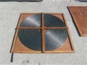
I don't think the black irrigation tubing used can handle the water inside freezing, which means the entire coil must be drained in the fall. I don't see a way to do this without disassembling the whole thing. I've been thinking of a plan to use a grid of black tubing mounted at an angle so all the pipes can drain to a low point. Add a vent at the high point and a drain at the low point, and you can now easily drain the system. The problem is the Tees and elbows significantly add to the cost.

The other solution I have seen is to use a flexible tubing that can handle freezing. I have not seen pricing, but for comparison, I would get a quote from
http://www.h2otsun.com/index.html

Happy Swimming!
10 years ago
On the contrary - This has not been a waste of time at all! I have learned a lot. and have been able to understand what is not practical, and what might be practical in the future, all without "getting my hands dirty", and without spending a dime (which, unfortunately, is really important at the moment, since I don't have many dimes). These forums are a great way to pick the brains of people with real practical experience. Thank you both!

Since the RMH water heater design is not feasible for my present small project, I came up with an alternate solar design. The materials cost is a more manageable $250. It won't heat the greenhouse, but it could save approximately $400 per winter in aquaponics water heating. If I get a chance to build it and test it, I will post the results on the aquaponics forum.

Cheers!
10 years ago
I worked up a preliminary design of the most likely plan, and came up with a preliminary materials cost using materials from Home Depot & Amazon. Bottom line is it is too costly for my friend's small hobby greenhouse (200 square feet), but I will keep it in mind as I consider larger greenhouses. Here's a description of the design -

A small 6ft X 8 ft shed ($218 at Home Depot) will be used to house the RMH. The shed has a plywood floor over a frame. I would start with gravel on the ground, then lay the floor supports, but place concrete blocks directly on the gravel (between floor supports) to support the fire pit and HW tank. After finishing the construction of the RMH, I would add plywood for the remaining floor area, and then build the shed around the finished RMH.

I envision the fire pit built inside a 2 ft X 4 ft X 1 ft tall wooden box lined with foil. The fire pit is built with fire bricks and cob, with a 6" clay flue liner as feed tube, and a rectangular flue liner used for ash cleanout. The ash cleanout needs a door (TBD). The riser is made from 4" stove pipe inside an 8" stovepipe with clay and perlite mix sandwiched between them. The riser is long enough to reach the height of the top of a gas HW heater. At the top of the riser, the exhaust gas is routed into the top of the HW heater vent opening using two 90 degree elbows and a reducer to fit the 3" gas HW heater vent. Stone wool insulation is used to cover the riser and stove pipe sections. The "air inlet" opening at bottom of the gas HW heater (with burner removed) is connected to more stove pipe elbows to the final stove pipe that exits the shed.

Since the gas HW heater vent pipe is 3" I.D., a fan will likely be needed to keep sufficient airflow through the RMH combustion chamber. The simplest solution is to use a stovepipe auto-draft fan that fits a 4" stovepipe ($154 on Amazon) on the last section of stove pipe. An alternate (and possibly cheaper) idea is to put an airtight door on the feeder tube with a fan that blows air through the feeder tube.

A small reservoir water tank is placed above the height of the top of the gas HW heater for expansion and venting. This system is NOT pressurized (for safety). It is filled with non-toxic anti-freeze solution that will be pumped through radiators for heat transfer. Two 1/25 HP Grundfos HW circulation pumps are used - One to pump water through hydronic baseboard radiators in the greenhouse, and the other to pump HW through plastic (Pex) pipe submerged in the fish tank to heat the fish tank water.

My preliminary materials cost is over $1200, with the most expensive pieces being the shed, stovepipe fan, circulation pumps, then stove pipes and fittings and stone wool insulation.
10 years ago
Alan, you mentioned -
"All doors and clean outs should be air tight !"

I found some nice rectangular and some round clay flue liner pipes online. I haven't yet checked local stores. The rectangular would work really well for ash clean out access. How would you make an airtight door on the end of either of the clay pipes?
10 years ago
I did get the P.M. and I read the thread on long feeding tubes. Thanks!

With regards to "Boom - Squish" - The RMH I have seen with stainless tubing inside the barrel is an open venting system. The fish water is pumped through the stainless tubing and dumped back in the fish tank (or possibly a mixer tank before entering the fish tank). Pressure cannot build up. He experimented some before building his system for his fish tank, so he likely limits the length of tubing to keep from overheating the water. The problem I see with this approach is the heating only occurs while the fire is burning - i.e. any thermal storage is in the fish water itself. It is not healthy for the fish to raise the water temp too rapidly, and you have to compensate for any overnight temp drop during the morning burn. If I tried this design, I might still want to use a separate insulated tank that I could heat quickly (without endangering the fish), and use the heat as needed to reheat the fish water.

With regards to the "Downdraft through water heater" idea as possibly performing the same function as the upturned barrel - I see what you are talking about. Also using the fan to push cold air does simplify things greatly. As far as the problem with a steel feeding tube that overheats - If you used ceramic pipe (I thought these were used as chimney flue liner - but I can't find it on Home depot site) would that solve the problem, or would the wood in the feed tube ignite too far up? Originally George sealed his feeding tube so there was no oxygen, thus no burn, but wood gas and smoke built up and was released when the feed tube was opened, so he used his fan to blow fresh air into the feed tube door to keep the gas flushed out. He uses a heat exchanger on the outside of the lower portion of his feed pipe to keep it cool enough to prevent the fire from creeping up the feed tube. I guess the air flow also keeps flames moving away from the feed door. If I had an inlet fan strong enough to push the air through the smaller tank flue pipe, I might need an airtight door for ash removal as well as one on the feeder door, since the fire pit area will be slightly pressurized.

The oil-fired water heater is a great idea - but I have never seen this type of water heater in north Alabama, so finding one used will be highly unlikely.


10 years ago
Light Bulb just lit up -

A) I understood that a hot riser was needed to induce the draft for a rocket stove, but did not understand that the barrel was part of the system - so the cooling effect in the barrel (compared to the hot riser) creates the suction needed to pull air through the whole system. That means if I don't use a barrel, I will need a fan to artificially pull the air through. In that case I don't need a riser either, and can simply mount the first water heater tank directly above the fire pit. The fan speed will also determine how hot the fire burns (Which may be a concern - I don't want to melt the gas HW heater!). If I knew for certain the exhaust gases would be well cooled by the time they exit the chimney, I could use a cheap duct in-line fan (<$30), but the chimney auto-draft fan has variable speed that could be useful. Has anyone measured the CFM flow from a properly working rocket stove? I also would want to add a thermostat and/or timer so the fan cuts off after the fire goes out so we don't end up cooling all that hot water.

B) With aquaponics, we never allow copper to come in contact with the fish water - the water is well aerated and would oxidize the copper, poisoning the fish and plants! Instead, I would pump the hot anti-freeze water from the heater through plastic (or stainless steel) tubing submerged in the water. I have also seen a working RMH with stainless tubing inside the barrel used to heat the fish water directly. Since the pump is pushing cool water, an ordinary pond pump can be used, rather than the heat-tolerant pump I would have to use. The only hazard is the fish water tends to have a fair amount of crud that I worry would cook inside the stainless tubing and clog it. So far the system I saw has not had that problem. His "fish house" is adjacent to the greenhouse, and he can move warm air from the fish-house into the greenhouse. I still may want to consider a similar setup.

C) I forgot to mention - I have no welding skills. The Mother-Earth article I saw that explains how to modify a gas HW heater to use wood fuel suggests cutting out the flue vent and installing a larger diameter flue. That's not within my capabilities. I wonder what that would cost at a welding shop?

So - Now I will compare two designs for cost and effectiveness -

I) The first design uses a gas HW heater over a rocket fire pit with a chimney auto-draft fan, and HW circulating pump to hydronic radiators in the greenhouse (with controls for the fan and pump) all inside a small shed next to the greenhouse.

II) The second option is to build a regular RMH in an insulated shed adjacent to the greenhouse using stainless tubing in the barrel to heat the fish water, and circulating fans to move warm air from the RMH shed into the greenhouse.

My instinct is the second option is more likely to work well.
10 years ago
Clarifications -
1) The proposed location is at a home (either where I live, or a friend's house who has an aquaponics greenhouse.)
2) One great advantage to an RMH is that you don't have to keep a fire running all the time. The heat from the short (but intense) burn is stored in the mass to be used throughout the day.
3) The reason I chose a 6 inch rocket was that I saw somewhere that smaller rockets perform poorly. I need to get the book to understand more fully.
4) I had considered using dampers on the cooler exit (bottom) of each water heater to be manually adjusted according to approximate tank temp in case one tank seemed to be getting most of the heat. In my mind this is a once a day adjustment until an approximate equal distribution is seen. I planned on connecting them all in parallel to provide the same total flue pipe cross-section area as a 6 inch pipe. Using a single tank would limit the storage somewhat, but would make things MUCH easier. Even using two tanks in series with an exhaust fan would be simpler than trying to fine-tune a manifold. I need to research vent fans that can handle some heat.
5) The flue baffle looks like it might restrict flow - I could be wrong. I am going by product pictures on retail sites.
6) I think you are correct about needing a shed. Unfortunately that just significantly increased the total cost.
10 years ago
Disclaimer - I have zero hands-on experience.

I'm looking at the idea of using water as the thermal mass in an RMH for a couple of reasons:
A) Water is a great thermal mass, and can be pumped to where it is needed.
B) I am a renter at the moment, and I cannot imagine a landlord that would say "You want to build a heavy experimental wood-fired furnace inside the rental home? No problem!". An outdoor water heater can be built a safe distance from the home, with hydronic radiators in the home.
C) I am experimenting with aquaponics. Hot water can be pumped through plastic pex tubing in the fish tanks to transfer heat safely to the fish water.

I propose -
1) Use four recycled gas water heaters with their burners and flue baffles removed. Gas water heaters have a 3 inch flue vent running up through their center through which the RMH flue gas could be piped to heat the water. The cross section of a 3 inch diameter circle is 1/4 the area of the 6 inch riser pipe, so the flue pipe should be split to the four tanks to keep from restricting the flow of exhaust gas.
2) The design does not use a barrel, just the 6 inch (Internal diameter) metal sandwich riser (6 inch metal pipe inside 10 inch metal pipe with perlite insulating between pipes) from the fire box up to a manifold built from 6" stove pipe tees and reducers to the top of the water heater gas vents. The hot exhaust gas enters the top of the water heater vents and flows down the internal vents, heating the water as it flows. The hottest gas heats the water at the top of the tank, making the most efficient use of the gas flow. Cooled exhaust vents from the bottom of the water heaters.The riser "sandwich" and stove pipe is to be covered with high temperature blanket insulation.
3) For safety, this will be a non-pressurized system with a reservoir mounted above the height of the water heaters. The entire system is filled with a non-toxic anti-freeze solution.
4) A hot water recirculating pump (with a thermostat) is used to pump the hot water through radiators located in the area to be heated.

As far as I can find, this idea has never been tried, so I would like to see what potential problems you might think of, as well as ideas for minimal cost.
10 years ago