Ed Kelly

+ Follow
since Jan 11, 2016
Merit badge: bb list bbv list
For More
Apples and Likes
Apples
Total received
In last 30 days
0
Forums and Threads

Recent posts by Ed Kelly

Satamax Antone wrote:Hope this will be of some help.


Those are all good thoughts. Thanks for all your help. I'll bee looking at these links.
BTW: I've not commented on the concern for a new chimney but I will be doing that. I may simply continue it underground and bring it up outside. If I'm going to insulate it there is no need for it to remain in the greenhouse. Then I'll run it through the roof at that time. Thanks also for the thought on the more room about the heat riser. It looks like I'll be redoing that as well.

F Styles: I actually thought this morning about creosote sealing those seams. Rather then using a mirror to look down a 24' black hole I will take the flue apart to be sure. Thanks for your insight!
9 years ago

Glenn Herbert wrote:The critical part is the proportions of the batch box and its connection to the riser, and you can find formulas for that at http://donkey32.proboards.com/thread/734/peterberg-batch-box-dimensions.


I've loaded his formula into my spread sheet and have already been playing with the Batch Box size.
9 years ago

F Styles wrote:Can you lift off your chimney and use a flash light to look down to the bottom of the elbow and see if there is condensation?


I may be able to put a mirror down the 8x9 channel leading down to the flue to look in there. I don't know however that any substantial water would be able to collect down in the flue. Because this sump is dug two feet down I had a situation with rain water collecting. This greenhouse is up against a 90' hi hill. I used a tire wall to hold the dirt back. The wall is in the greenhouse and can be seen in the pictures. When I built the wall I dug a french drain under it and filled it with creek gravel. The wall sits on the gravel. When it rains this drain fills with water. I found that in a good rain the water could backup into the sump area and get under my liner filling the flue. This being a potential issue I installed a bilge pump a foot lower then the sump's bottom. The bilge pump draws it's water from a gravel channel (the beginnings of which can be seen in the first picture below) running the length of the sump. I also was concerned that should my liner develop a leak it would fill the flue and begin corrosion especially if this happened in the summer when I'm not using the heater. It would never dry out. So in the final stages of the sump's bottom I dug several channels that lead from the center cavity where the flue rests down to the bilge's gravel channel. They are located at the two connections of the 24' flue which are two lowest points of the flue. Any moisture would run to these seams and slowly drain out there. I know my "Bilge" is always dry as I'm regularly checking that.

BTW: When I was saying "the heat riser is only half as hi as the double barrels" I was referencing the 8" Batch Box that Glenn linked me to. My system currently uses a heat riser over 60" hi.

Glenn Herbert wrote:Looking at your system photos, I think you could build a batch box to replace your existing burn tunnel/feed area, connecting to the existing riser, without touching the rest of the system. You might need to lower the floor, or if not practical, cut a notch in the barrel and raise the top of the firebox from where it is now.


Thank you Glenn! I'm liking the sound of that. Let me show some pictures that may help you guys see what I'd need to fit this new design to. The more I can keep what I've got the better. But I'm thinking things are not going to be that simple.


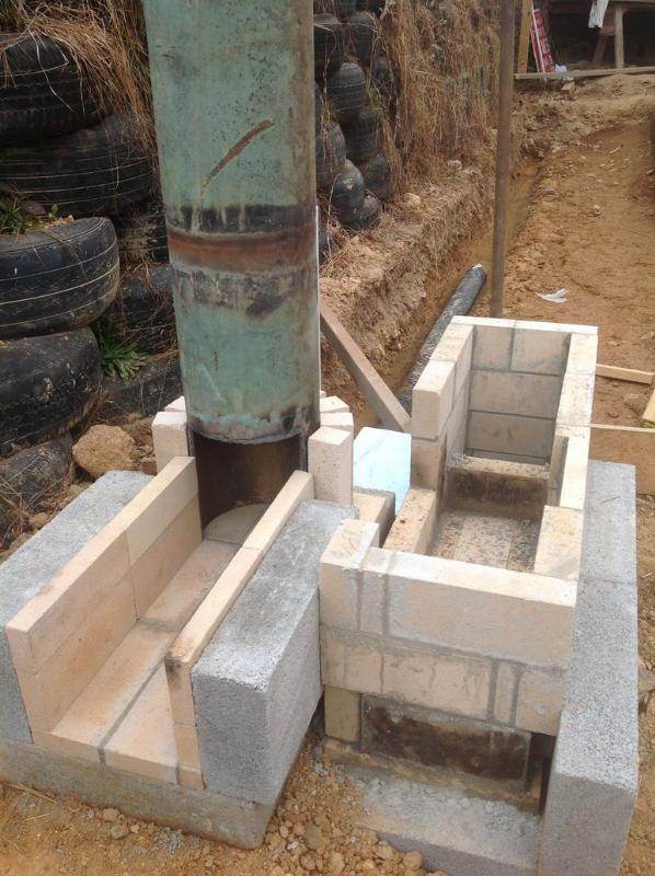
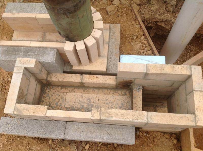
Above is a view of how the fire tunnel joins the heat riser. The heat riser is so tall and heavy I was uncomfortable leaving it supported by only cob around a few fire bricks. So concrete was used to fill in all the way around the base of the heat riser. This picture was taken before the lower ash pit was dug out in front of the fire tunnel.


This picture shows a better view of the fire bricks surrounding the carbon steel heat riser. Concrete is now poured around those bricks to help support the heat riser.

Glenn Herbert wrote:Something I have not seen is a mention of how you have insulated the bottom of the duct under the tank.


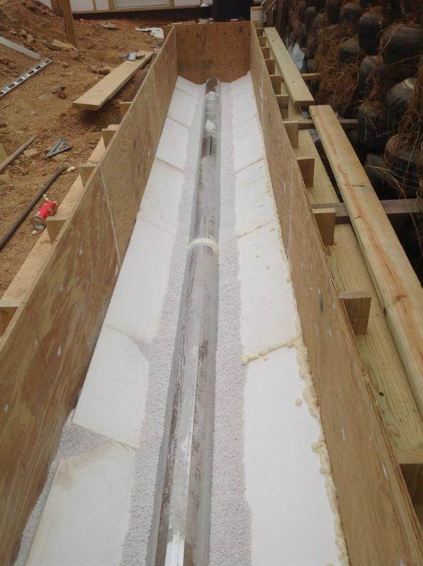
There is at least 2" of foam under the liner. The foam stops a couple inches short of the flue where vermiculite takes over. The vermiculite fills and lines the channel where the flue is. When I first ran the heater a year ago I got a good idea of how it drafted and acted under certain conditions. But when I filled the sump with water the stove acted more sluggish. I found that the water weight was actually compressing the flue by about and inch or two. When I emptied the sump again the stove operated as it had before. My solution was to remove a good deal of the vermiculite at the bottom of the sump around the flue to let the liner press in closer to the bottom of the flue allowing the water pressure to support it's original shape. That seems to be working much better. Although I have been concerned that the foam may be compressing a bit thereby reshaping the flue into that oval shape again. But the stove does seem to be operating as it did before now.

Below is a picture of the finished sump before the liner was put down. This picture was taken before most of the vermiculite was removed from around the flue.
9 years ago

Satamax Antone wrote:Ed, another tube around your existing one, and fibergass batt or roxul is perfectly fine. And realy you will need to extend your chimney.


Am I raising the chimney higher then any "Buildings" within a 50' radius in order to get above any obstructions to a breeze or wind? I'm located in a rather tight bowl between hills all around me. Two of them are both within the 50' limit you speak of. The winds here can from time to time be quit influencing and for the most part unavoidable.
9 years ago

John McDoodle wrote:May I ask your clay:vermiculite (mass:insulation)ratio around your steel riser?


It's actually been over a year since I made this stove so I don't remember for sure. I do remember however tearing down the first insulation around the heat riser because I felt as, you have pointed out, there was not enough air in the mixture. I've thought about increasing the air in the insulation even more.

John McDoodle wrote:Have you tested the core by itself for performace/issues. I'm sure the insulated chimney sure would help a lot as others mentioned also. A mass like that sure would take a long time.
Also curious, why the two 90 elbows and 3' horizontal exhaust, after the 9' vertical, but I guess you have to go thru a wall there, so you should have more vertical pipe after that?


If you are speaking of removing the barrel to see how well the foundational system draws I can not. This is in a green house. If you notice in the second picture of the entire system the ceiling is plastic. I was initially thinking to keep as much heat in the building as possible so I kept the rising chimney inside. Then I needed to get it outside but rather then go through the plastic ceiling and roof I took it though the wall.
Is the main reason for insulating the chimney an effort to keep any remaining heat in the chimney thereby adding in the flow upward? At this point I'm ashamed to say there is no more pipe after it gets to the other side of the wall. At the moment the exhaust is simply expelled under and overhang out there. Going through the roof would involve some other issues I've yet to address. But to start with what would I insulate the chimney with? Fiberglass?

Glenn Herbert wrote:Successful perlite-clay mixes I have done have been somewhere around 5-10 times as much perlite as clay by volume. I don't premeasure, but dust powdered clay on dampened perlite, mix, and repeat until all the perlite grains are covered with clay and it can form a solid snowball that pops with firm finger pressure. This mix becomes quite strong when fired.


Thanks Glenn for you perlite-clay mixes. As to a batch box I have seen this about a year ago but not the post you referenced above. THANKS again for that link also. The size of the green house is 36' x 40' with the RMH set to one side. I'm needing to set the heat riser to one side like I have it now for the purpose of directing the heat into the room? I don't think the design I found at that link you gave above would do that. The heat riser is only half the hight of the double barrel hight. Also I've got a plastic ceiling over this whole thing. I currently have a heat deflector hanging overhead but may need to beef that up a bit. I do like the overall idea of the Batch Box and am sure the extra space in the top of the barrel is needed.
9 years ago
Well hello all…

I’m having some difficulties with a RMH I’ve built for an aquaponics green house I’m constructing. I’ve got so many figures in my head and I want to only bother you fine folks with the facts you need to properly analyze my situation. Of course I’ll be happy to answer any questions you may have about my use and build as they are posted.

I purchased the book by Evans & Jackson a couple years ago and have largely tried to base my construction on the “science” in that book. I have obviously strayed from the main design in that book as I have some rather special features I’m needing to incorporate. It would appear however I’m missing or have yet to incorporate some important aspects of the RMH in my design.

I intend to use this RMH to heat water in an aquaponics greenhouse. The exhaust is buried under a 1500 gallon sump using an 8” pipe. The water will not only heat the fish tank it's pumped to but eventually all the grow media rocks used in the four 4’ x 20’ grow beds. I’m sure it will take a considerable amount of time to stabilize all this mass. But I’m hoping it will also hold onto that temperature once it has captured it.

I’ll post some pictures and try to briefly explain…


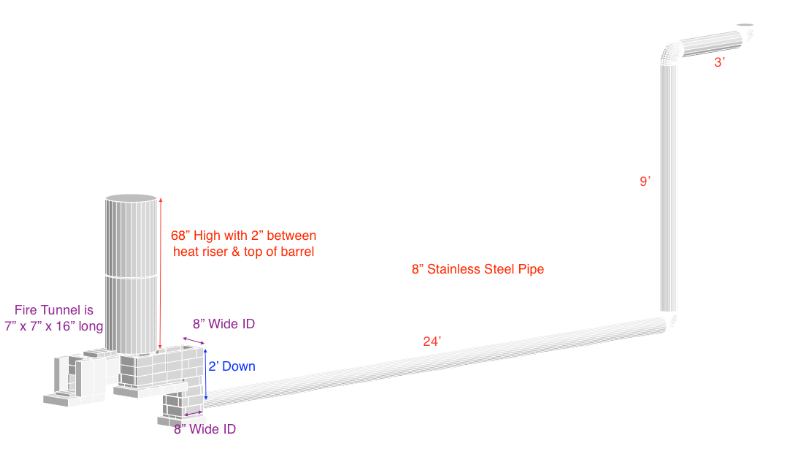
Above is a CAD of my basic design. The exhaust or horizontal flue sets 2’ under water. It runs under a 24’ long body of water before rising 9’ feet and then through the wall. At the moment the flue stops there just outside the wall under an overhang outside. I have played with the idea of placing a fan out there to help the draw. The heat riser is made of an 8” steel pipe 1/4” thick. It is insulated with the vermiculite/clay mixture described in the book. The insulation is 3.75” around the heat riser. There is at least a 2” space between the heat riser and the top of the capping barrel, there may be more. The heat riser is also completely offset in the barrel to reflect the heat toward the inside of the greenhouse. It also directs the flow strait down into the ash pit area. It then moves over to where it will go down 2’ below the water. When the heater is running well the pipe at the other end is cool enough to put your hand on. It’s only barely warm with the smoke wafting out lazily.


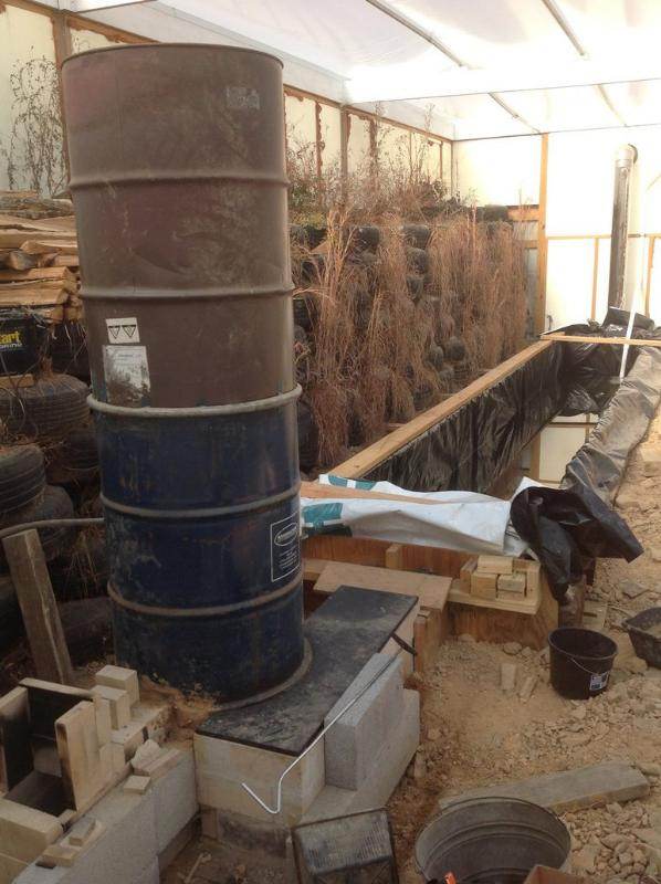
Above is a view of the system as it is now. In the distance the 9’ pipe up the wall can be seen. Coming forward is the 24’ sump of water. In the foreground is were the main RMH can be seen. The ash pit and 8” x 9” (the 8” Wide ID label at the bottom of the CAD picture should read 9”) square channel where the exhaust goes down under the water is covered with a 1/4” steel plate.


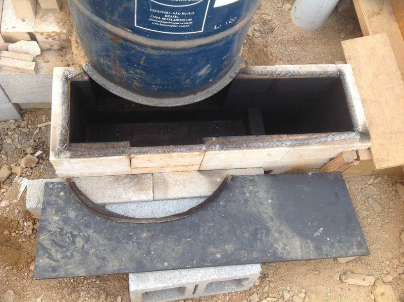
The above picture is a view with the 1/4” steel plate removed for clarity. The narrower fire bricks seen in the middle was where I planned to introduce another exhaust pipe should I need to redirect heat if the water in the sump was getting to hot. At this point I don’t see it being needed.


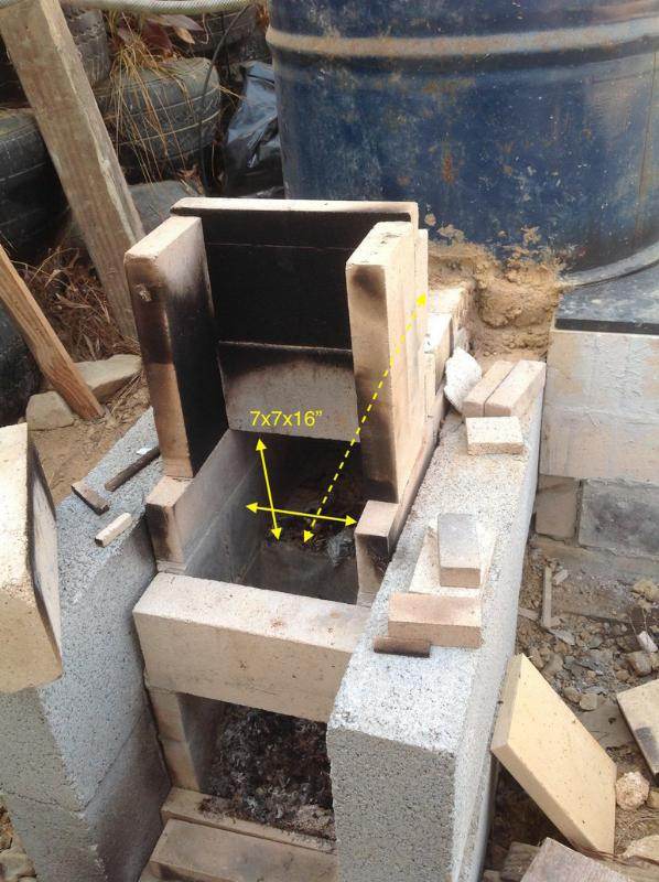
Above is a closer view of the current fire tunnel and feed area of the system. This is obviously were I’ve been experimenting and playing with different ideas. Generally the stove is easy to start with little or no smoke. I usually start a fire just inside the fire tunnel. As it is getting started I’ll blow a little to encourage the heat up the riser and that’s usually enough to get things started. The lower area is a clean out area. My thought was to use a stainless steel grid or grate that spans from the end of the fire tunnel over this ash clean-out area. As wood burned it would fall through the grate and could be easily cleaned out there.

The Main Issue…
I think the main problem I’m having is not enough draw to start with. If there is much breeze or wind outside, the draft is easily overcome and smoke begins filling the greenhouse. As is visible I’ve played with different feed tube designs but inevitably have had to cap them off to keep the smoke and eventually fire from coming out the feed tube. I’ve actually been using the capped feed tube as a place to hold sticks of wood that gravity feed down into the ash pit area where they burn there. Oxygen is supplied down at the door of the ash pit. I’m aware that I need to better seal and insulate this fire tunnel area but was wanting helpful input as to move me in the write direction or even point out some concerns elsewhere before I proceeded. I may even have to rebuild something (perish the thought).

Also at times when the stove is running well, I need to feed it about every 45 minutes if I’m to keep the rocket going. Any ideas on getting a halfway decent nights sleep in the wintertime? I have had some thoughts myself but am interested in yours out there. I was thinking the feed tunnel could be lengthened to allow longer sticks of wood to be used as fuel. That will not work however if the fire is just going to work it’s way right up the feed tube.

There is much more information I could give but think I’ll wait for questions and answer those.

Thanks again for all your insight!
9 years ago