

|

|
|
|
|
 He's been a furniture maker, mold maker, composites specialist, quality inspector, master of boats. Roughly during the last 30 years he's been meddling with castable refractories and mass heaters. Built a dozen in different guises but never got it as far as to do it professionaly. He loves to try out new ideas, tested those by using a gas analizer.
Matthew Galloway wrote:Ah 30cm thick ceramic fiber was a mistake - I meant 30mm!
There is 10, 20, 25, 30, 40mm high temp ceramic fiber blanket available here. I could do 20mm or 25mm if you think that is sufficient instead of 30mm.
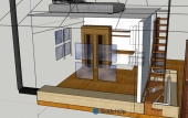
Matthew Galloway wrote:Ah I didn't understand the the depth/length of the firebox could be extended. In the Sketchup design it made it to exactly 376mm from the backside of the door to the front wall of the port wall, but if it's recommended to be larger to provide more space for wood positioning, I can adjust my design.
The common length of firewood around here is only 30m, so maybe I'll bump up the depth of the firebox to 430mm. How does that sound?
Matthew Galloway wrote:You make a good point about stability especially since effectively this batch box will be raised 80cm above the ground to match the floor level, making it more vulnerable than a masonry heater closer to the ground level. The support bricks below the subfloor will all be mortared on the 15cm face for stability, but perhaps I will reconsider the bell design to utilize the stability of the 15cm clay brick face for the bell walls.
Matthew Galloway wrote:I do still intend on building the core on the 6cm face of the refractory brick, but I can reinforce that with a steel frame.
Since we're on the subject, do you think it's necessary to place a layer of clay brick alongside the sidewalls of the core or is it sufficient to just have the steel frame and wrap the core and riser in ceramic blanket? I'm thinking 30cm thick ceramic superwool.
Matthew Galloway wrote:
Now I'm working on the bell and realizing with the 30x15x6cm clay bricks available here that would suggest stacking the bell bricks on the 6cm edge to keep the profile of the bell as small as possible. So I'm going for a cube shape of about 90x90x90cm on the exterior. Is stacking on a 6cm edge with clay bricks reasonable or should I change my design to stack on the 15cm face instead?
Matthew Galloway wrote:I'm just under the Shorty ISA for 130mm at 3.38m2 (adjusted for shorty) if I stack clay bricks on edge, with the bottom of the core 26cm from the bottom of the floor, and with 30cm of air gap on both sides between the inner walls of the bell and outer walls of the core. I'm also assuming with a shorty it's ok to have the ceiling of the riser in contact with the ceiling of the bell, but if this isn't advised I'll adjust the design to be a bit taller and narrower.
Aeron Ironbark wrote:- Core material: insulated fire brick vs ceramic fibre board (vs something else)? What's the cheapest and easiest? And is longevity/durability the exchange for that?
Aeron Ironbark wrote:- Location of the flue: I've seen brick RMH's with flues inside the bell, and I've seen them outside. It seems to me that if it was inside, as soon as the burn starts it would begin heating the flue and starting draw, thus minimising (or eliminating) smoke coming into the room. However, it seems to me that this setup would also create quite a strong draw during the main burns, and would thus be drawing out hot gasses before they had given their heat to the bricks, thus making the system much less efficient. Conversely, the flue on the outside means that only gasses cool enough to reach the bottom would ever make it to the outlet, which would mean much more efficiency in terms of heat given to the thermal battery, but how does the draw start in that set up? I've been thinking about a Tee piece at the outlet, and putting in some wood shavings at the start of a burn to heat up the chimney directly? And how does the draw continue? As I understand, any flue situation relies on the temperature differential between the pipe and the surroundings, and in the scenario where the pipe is outside of the heater, and the outlet of the heater is at the bottom because that's where the coolest gasses end up after giving their heat to the brick and thus making the thermal battery a thermal battery, how does the draw maintain?
Aeron Ironbark wrote:- Secondary air inlet: Does this piece of square tubing have to just be a replacement part, since it will sit directly underneath the primary burn chamber and be much hotter than steel is designed to get? I've heard of fancy expensive metals that can be used to make tubes out of, but I think in Australia it's hard to get. Love to know what folks use for this.
Aeron Ironbark wrote:- Sizing the Bell: If i've read the tables correctly, if i go with a 200mm riser, I need a Bell with a 9.4m2 internal total surface area. I've read about people adding columns inside the bell to add surface area, which sounds like a good idea to me to keep overall size down. I've also been hoping to do it as a single skin for the same reason, but is that a bad idea?
Aeron Ironbark wrote:- Bell lid material: What do I make the lid of the bell out of?? I've got the business end of a rocket stove pointed directly at this thing, and I can't find info about what it should be made of... I don't know much about concrete, but it seems like it would just crack? And what does it sit on for support across the span? Another reason I like the flue on the outside is a simpler construction of the lid, so there's that too...
Aeron Ironbark wrote:- Bricks and mortar: What bricks for the actual Bell? Plain old building bricks? Solid/vs hollow? And what about the mortar, both for the core and for the bell?
Matthew Galloway wrote:Here's the part that I'm not clearly understanding from the instructions:
"Equally, if the firebox is built into the bell then the surface area of the firebox within the bell won't play a role in calculating this area as no heat is absorbed there."
Is he referring the SA of the firebox itself or the walls of the bell that surround it?