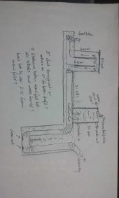
Tried sev times to attach a sketch but (on my phone) does not serm to work.
So here the more cumbersome verbal picture.
Take the standard drawing/ design of a basic RMH. 2 - 3 feet along the flow duct/ bench, away from the burn site, picture a second barrel, 30 gal size?, sitting directly (with supports so it does not crush the duct(s)) atop the ducts and being heated by radiating heay from them. Has to be sealed well all round of course. Then the ducts proceed through the bench as is stsndard and exit bwo chimney.
Reason I came to this design is reading in this forum how tricky, high tech (by my definition), and potentially dangerous it is to install a bot water devise closer to or around the riser/barrel.
Logically, the air would have cooled a few feet away from the combustion chamber and, second barrel sitting on top (though insulated), would receive considerably less heat so that a float level control and pressure relief valve may be all the safety prep it needs. Barrel would have water in and outlets, and likely a pump to trandport it to its places of use.
I'll try uploading the sketch again if/when I get to a PC. Perhaps what's presented here is vlear enough for a few constructive, critical comments.
Thanks much.


 ..... and questions. Is anyone aware of the existence of a "dual-fired" (for lack of a better term) RMH, i.e. with firing and combustion set up at each end but sharing the tubing inside the cob/mass heat storage/ structure ("bench, bed, etc.) and exhaust? I haven't thought this completely through and have not the technical oversight of such an arrangement, so wondering on consensus in the community???