Mark Miner

gardener
+ Follow
since Mar 18, 2020
Merit badge: bb list bbv list
Biography
Now in the PNW on the dry side, big family, special needs kids, Orthodox Christian, thankful for lots, trying to keep learning and doing.
For More
PNW Steppe climate, not far from the big river.
Apples and Likes
Apples
Total received
In last 30 days
9
Forums and Threads

Recent posts by Mark Miner

Thanks all for the kind words.
Cristobal, it is 330 alloy, sorry I anagrammed the number, but it is rated to 2500ishF, so I do hope for good service in that position.

Thomas, you are on the right side of that position, no doubt. Heigh ho for elbow grease!

We are enjoying a thoroughly saturated warm mass for Christmas. Hope you are all happily heated this season!
1 week ago
Hello again,

Silence was not inaction. The RMH is up and running, commissioned on the last day of fall, so I "got it done before winter" by about 4hrs. It has been a busy fall, both with this and all the other projects (not to mention work), so I am sorry for the lack of in-process posts, but this way all my mistakes can be solely blamed on myself.

We've been burning it over the past few days, and gathering data from the thermocouples, and I am pleased to report that it seems to be working, and even more pleased that my wife agrees that it seems to be working. For lack of a properly formatted SD card (or maybe a small-enough one, my reader is old), I do not have the temperature graphs ready yet, but those will be forthcoming after I fiddle it into cooperation.  We burned a batch around 9pm, and this morning at 6am the outer skin was ~25degC and the inner temperatures were still in the 60-70degC range. I was quite pleased.

I must again thank Peter, Thomas, and Glenn in particular for your excellent advice and guidance, whether or not you knew you were giving it. Glenn's build (linked in Thomas' post above) was the nearest template to what I wanted, and where I have differed, I will take blame for failure; where I have followed, I will give him credit for success.

The final outer bell size is about 3.5ft wide, 6ft high, and 4ft deep, made of clay common brick. Most of the outer bell is mortared with regular Type S masonry mortar, there are a few places near the firebox door where I used Rutland refractory cement. Yes, the masonry is not pretty, that's my doing, we may clean it with an acid and scrub to get it red again (my wife's preference) or plaster it (my preference), but right now it is what it is.

The two K-type thermocouples monitoring it are positioned roughly above the inner bell riser and roughly on top of the insulated firebox (just inside the outer bell skin there, it will become clearer with photos), and we are now getting burn temperatures about 580degC at the top of the riser, and up to about 150degC on the top of the firebox. The outer mass seems to have fully dried after about 3 days of use, and is a pleasant 25-35degC. Here is a short video of it burning: [youtube]https://youtube.com/shorts/xKOSKjSKZBs[/youtube]

The photos are numbered in sequence of the build, and I am supplying a short caption for each.

1) The layout on the floor, loose. I started with a plinth support for the core, but abandoned that in favor of a metal rack for better dimensional control over the core floor height and for cleanout access.

2) Old stovepipe from the wood stove, with a rectangular aperture cut in it to allow the air nearest the floor to come in. Rectangular apertures can be treated equivalent to circular by making the hydraulic diameter (Dh) match, where Dh = 4* A / P where A is the hole area and P the perimeter.

3) The cleanout is a stainless blast gate from Zoro, it didn't have to be that fancy (it's cool down there, relatively speaking), but I like it. This was a major reason to ditch the plinth support and have legs. I can get a shop vac tool all around the bottom now.

4) The basket for the core, which has six legs and also rests on the inner bell walls. Note that I only have a single layer of brick at the front at this point, which is a departure from Glenn's plan. Time will tell whether that was a reasonable call or not, but you will see a double front further up.

5) The door frame, which has its own legs on the floor, and also ties into the core basket with bolts for stability, somewhat hard to see, but they drop into the wide crossbar at the back of the core support, and make an angle brace for the front door support legs, which are nice and stiff.

6) The core takes shape, following Peter's 6in dimensions. Very thin fireclay in the joints, which was a surprisingly fun material to work with, way nicer than the refractory mortar.

7) Assembled core, and I did choose a notched brick arch for the top, it kept the same perimeter of the core, and avoided casting a slab. This did not change the door aperture size, which remains rectangular following Thomas' plans.

8) 1.5in Superwool all around the core, tied on with stainless wire.

9) Here is where I accommodate the arch with a pretty aggressive corbel. I do have a steel plate supporting the top, and this is all done with refractory mortar, since it gets warm, though not, so far, above 160degC, which is not a significant stress on the concrete. This is a very good article about Portland at elevated temperatures (but NOT firebox temperatures!): courtesy of Periodica Polytechnica Civil Engineering.

10) Here, above the body of the core, I add a front face to the inner bell, and transition to firebrick for it. This rides on angle iron, which is supported on the inner bell common brick as well as with a support leg resting on the door support angle iron, so there should be good support all across the span, which is only 25in. The second thermocouple tip is located just below this support beam, more or less on the superwool on top of the core, just inside the single-layer common brick front wall. I wanted to know how hard I was stressing this beam, and so far, so good, it's peaked at about 160degC as noted above.

11) Here you can see the superwool trimmed to the riser top, and the firebrick inner bell growing.

12) Here is where I checked all my interior surface area calculations for the last time, which required one more layer of firebrick to hit the 57sq.ft goal. The final ISA came out as 57.6sqft, though I did not calculate error bars on the value.

13) Many thanks to Thomas Rubino for his excellent and very usable door plan and parts kit. The snotty welding is my own failing, but the design is great.

14) The top is built a little differently, so it may be worth a few words and pictures. Glenn's design has his riser exhausting against the angle iron which supports his uppermost firebrick layer. This did not sit well with me (though I won't knock his design in the least!! accept this as my engineering neurosis). So, instead of layering it steel-brick-wool, I chose to layer it wool-steel-brick at the top, and I formed a basket of ultrahigh temperature stainless rods (303 series, I think, but $7/rod from McMaster, I used 9, not too bad). In this basket I laid my large piece of superwool. Exhaust gases from the riser will hit this refractory assembly first, and the steel angles which support the roof will not get so hot. Thus, the upper superwool is not used for sealing (as I believe Glenn's is), but is used for insulation. More on sealing later.

15) You can see my upper thermocouple wired to this stainless basket, located about over the exit to the riser - it's not exactly at the stagnation point of the flow, so it won't see quite the highest temperatures, but it will be quite close.

16) Another view of the basket and thermocouple.

17) Laying the superwool in the basket

18) I said I'd say more about sealing. The roof of the inner bell is not perfectly sealed, as the firebricks on their beams are set dry on a 1/8in gasket of superwool. The edges are stuffed with the same thin stuff, doubled, and this is not airtight.

19) The topmost common brick layer sits on a shelf I made on the outer bell by turning the topmost bricks on edge, and then sits on the firebrick inner bell top. I used more of the thin superwool to give it relief from shifting, and covered the angle iron joints with it. The top bricks laid in beautifully in integer rows, almost like math actually worked for me. Still not airtight.

20) Perhaps the most gratifying one. The first real wood fire in it, with the stovepipes hooked up and everything. The flames went back and it roared gently. It has gotten a deeper voice as it has grown up, er, dried out, and runs hotter now with a stronger draft. However, a modest but unpleasant amount of smoke oozed out the top.

21) Here was burn #1, which I did rather cautiously. I had actually put tea light candles in the core for a few days, just to start the dryout as I was completing the outer bell, and that may have helped season the surface a bit, but the burns have only heated up from this one.

22) So I fireclayed the top to stop the leakage, and that has been very effective. No more smoke.

23) And here it is with a much more respectable burn temperature. The stovepipe stays hand-touchable.

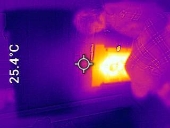
The following are FLIR camera shots, they are tiny, but fun.
24) Here's the stovepipe. The FLIR puts an averaged temperature number corresponding to the target circle region (+/-).

25) You can see the wet brick at the top, those were the last courses laid, and they are still cool in this frame.

26) The door gets warm. It's finally cured the high-temp paint, which was a bad smell for a while. I just used Krylon BBQ paint from Amazon.

27) Here is the large sidewall, quite comfortable and pretty well dried.

Time will be the test, of course, but so far, I am very thankful that this (long, long) project seems to be at a functional place. I have to tidy up the front with a better faceplate to hide some superwool around the door assembly, and I am sure there will be more to learn, but we're all enjoying the house being warmer now that the days are staying cold.

Happy heating,
Mark


1 week ago
Greetings,
I have not worked with stone such as you have (I have done lime-mortar work in soft brick), but I can confirm that Portland-based cement is not compatible with soft lime-based cements, which are typical in century-plus old construction. The Roman pozzolan cements put all modern materials to shame, in spite of being "weaker". Injecting a fine lime/sand glue mortar can be effective, but you do not want to inject at a high pressure (lest you float the joint), and you will get better penetration into the crack with modest vibration (but again, gently).  If the rock is lime-based, which seems likely enough in Greece, lime is more compatible. If the rock is granitic (which I hear happens in some places), then a more aggressive cement might be OK, but I think in all cases, lime would be an acceptable choice.

Epoxy + stainless will indeed create a new load path, which might help, but as Cristobal noted, this is somewhat likely to just shift load paths into unexpected places - as in, it will take a system that relied only on compression and cause some of it to rely on tension and bending (which stone does not like). Gravity compression of adjacent materials is going to develop better distribution of load against the wall. To avoid outward motion of the foundation, you need pressure, not strength, and you want it to be distributed evenly over the older materials. This could be done with concrete buttresses with a backfill against the wall, if you like how they look, or it could probably be done with rock-filled gabions, or other things, but in any case you probably do need to key some reinforcement into the ground/bedrock, so you get shear resistance, whether a footer trench or vertical pins (of steel or concrete), I can't guess from a distance. Cristobal's comment about using the new foundation as the retaining wall to buttress the old is quite reasonable.

I am a PE over here in the US, and for that reason, I urge you to take your engineer seriously, but not too seriously. Don't be shy about asking questions, doing your own research, finding other case studies, and talking them over in a conversational, curious manner. There are very few experts in this kind of thing, but remarkably, old buildings have survived quite a lot of expertise over the years. Keep clear in you head the important distinctions between pressure (distributed loads), forces (point loads), and strength (material properties), and aim for a gradual load path change - ie, a very strong material with high forces embedded in a weak material that requires pressure loads is risky. This sort of thing has a lot in common with putting pins in bone or putting nails in wood than with putting rebar in conventional concrete. The act of drilling for the reinforcement rods could itself cause unexpected problems. The sooner you can protect that exposed footing, though, the better. Godspeed! Kali dynami!

Mark


"Et facta est lux."
1 month ago
We've been in the house for one heating season, and the cured firewood that was left from the prior owners was pine. Soooo... soot.

Thankfully, the chimney is very easy to access from the bottom, a cleanout Tee is installed with an insulated plug, held in place by plumber's strap. Two screws out and the bottom is open. The garage trash can was handy, and I had some painter's plastic and tape that helped make a shroud/chute to bring all the junk into the trash can. It was a remarkably clean process thanks to that, and I only had to shop-vac a little bit of the garage.

The brush has a set of threaded extensions, which allow the cleaning to proceed about 4ft at a time. I learned that it is best to NOT reverse directions mid-push, as the steel bristles then have to buckle to flip their orientation. One run up and down was enough to knock out all the gunk, and left the chimney very respectable. I also pushed through from the other side, where the stove is (or was, a Rocket Mass Heater is in works), dumping all the ash in the trash through the film chute.

Happy homesteading!
Mark
2 months ago
This is a badge bit (BB) that is part of the PEP curriculum.  Completing this BB is part of getting the straw badge in Electricity and Plumbing

In this Badge Bit, you will install a deep well pump for potable pressurized water.  Hand pumping water is great exercise.  But maybe it's time to install a well pump:

Here's a video of a guy wiring a pump and getting it underground:


And one of the wiring bits by the pressure tank:


To complete this BB, the minimum requirements are:
  - perform the installation or replacement of a deep well pump
  - potable water
  - pressure controlled with a pressure tank
  - you can elect to do the electrical portion, plumbing portion or the full job

Electrical points earned vary from 4-8 points
  - 4 points if you are replacing a pump
  - 6 points if you are installing a full system (pump, pressure tank, breaker, wiring, trenching, etc)
  - 8 points for something excessively wonderful or complicated (this is very unlikely to be awarded)
  - no duplicate points for other sand or straw electricity badges like running the wire, adding the breaker, etc

Plumbing points earned vary from 4-8 points
  - 4 points for replacing a pump
  - 8 points for installing a pump where one didn't exist before
  - you can get certified for the "Replace a pressure tank" BB if you install a new one or replace the existing pressure tank

To show you've completed this Badge Bit, provide proof of the following as pics or video (less than two minutes):
  - well location before you start work
  - empty well casing
  - old pump (if applicable)
  - new pump wired and plumbed
  - wires coming out of cap after installation
  - planned pressure tank location (if applicable)
  - pressure tank wired (if applicable)
  - water flowing from a faucet or hose
2 months ago
I am sorry to hear that the design has been an ordeal. $25k for design is not something I would consider reasonable for a single family home, at least for a result that isn't a stupendous piece of architecture.

As far as roof and foundation, they certainly are significant costs, and your builder likely knows local conditions well, so I won't argue from a distance. That approach is why CA subdivision houses increasingly approximate Borg cubes. Lots depends on your climate, your preferences, etc., but saving the engineering fees can pay for fair bit of metal roof or concrete. Anyway, I don't know what you're balancing, family size, lot size, etc., but I'd encourage you to be pointed in your questions, and slow to pay for work that you don't want or need. You can ask the builder "what's the per square foot cost for foundations? roofs? walls?" and do some rough math yourself.

There's nothing wrong with yurts, but they are a pretty short-term solution, and don't leave you with any equity once they are worn out.  Again, it all depends on what you need, want, and can afford. I hate to say it, but the successful natural building people I know of are either tiny-house DIY'ers (frequently people in the trades or otherwise personally skilled, this is the set that tends to be represented on Permies) or... pretty wealthy.

Take it one day at a time, don't get too discouraged, but be careful about throwing good money after bad.

Best,
Mark
3 months ago

Patrick Graeme wrote:My question is, are those estimates of 2-5% based on having contractors do all the work?


Yes, that affects the denominator of the fraction. If you manage to volunteer lots of labor (that does a good job you don't have to repeat), or do a great deal yourself at a low opportunity cost, expect the percentage of preconstruction costs to go up. Knowing that you are in CA, and that you expect to have engineered plans for a custom design, I would encourage you to have between $10k-25k ready to deal with preconstruction. That's a big range, and a bit of a guess, but I know very few engineers who would do a custom 2-story timberframe/straw house engineered plan for less than $10k (I wouldn't, as I have a guess at how much of my time that would take up having done similar work for masonry-type designs). Since you want 2 stories, IRC Appendix S is less helpful, it would only apply to single story, and requires engineering for two levels.

To your other point about labor/materials for "a building", I think that may be an older impression. I would have agreed with it ca. 1990-2000. I observed labor/materials being roughly evenly split up to 2020. Post-inflation, materials dominate. This is a general observation based on conventional construction, and using a natural building approach can tilt the balance towards labor again, but not necessarily because you have drastically reduced material costs, just that you need a lot more labor.

Anyhow, if you are in a place where you can save and sock away money towards the project, that's a good thing to do until you are well-provided to go in with enough to get to dry-in at a minimum. Your straw does not want to be partially complete during a rainy season, so you really want to have enough funds to get quickly to the roof and exterior plaster before you could consider slowing down and doing things yourself more leisurely. You've got a pretty big wall area (guessing ~3600sqft), so getting exterior plaster up on that will take a while (and a lot of scaffolding), and you are tall enough that no roof eaves will shield the bales adequately from rain. You've said you worked with a designer, and have a plan you like, but please do consider that the costs of construction are determined in this phase. Single-level strawbale can save you a lot  of money and headache by allowing you to use IRC App. S (not an engineer), and will make your exterior wall work so much easier - a 2-3ft work platform is so much easier to work on than scaffolding. I've been a builder, and I am an engineer, and I will tell you that neither of those roles (or the designer) has the job of telling you "this might be an expensive idea" - all of those roles just charge more for complexity, and are typically happy to do so. Thus, as I have no personal stake in your project at all, I suggest you think hard about what you really need, and if you can live with a smaller or simpler plan.

It sounds like a cool project, and I wish you the best! I do encourage a careful counting of the cost, and starting the project with a "hope for best, plan for worst" approach.

Best,
Mark
3 months ago
Hi Rico,
Thanks! That is a perfect sketch to begin with. What are the 2 larger batteries doing? As drawn, all is well with your plan, and using an AC-powered charger to maintain the big batteries is fine in principal... but what for?

Also, looking at the back of your EcoFlow, I see 300W max AC output. That Victron 12V 25A charger would draw more than that (12V*25A = 300W, and you are never 100% efficient, and you are always charging over 12V...) Do make sure the charger you select will not overdraw your EcoFlow.

If you are hoping the EcoFlow can use the external battery in parallel with its internal battery, that seems to be a questionable hope. Maybe I am missing the point of the larger battery?

Best,
Mark
3 months ago
Hi Rico,
Thanks, I think I am beginning to put the pieces together, but a quick sketch of your overall system and design intent would go a long way...

Those BMS notes are 100% internal to that battery. You will never interact with the BMS that is buried in it. It's telling you that it is doing right by the LFP cells. However, the internal BMS of a sealed battery like that is better used as a backstop to serious system design errors. It's not your charge controller, it's not your disconnect, it's not doing anything except getting the manufacturer out of liability (and keeping the strings of 4 series cells inside balanced, which is super important).

Your interaction with that battery will be through the top terminals, and the question is how do you plan to take charge in and out, and control that?

Best,
Mark
3 months ago
I have that charger, and as you say, it is an AC-source charger. If that is what you need, it's a great tool. I use it as a bench maintenance charger.

If you want a solar-driven charger, that is not the unit for you. I believe Mr. Rubino has a solar charge controller from Victron (as you noted), which is the sun-to-battery device.

What are you trying to do with it?
3 months ago