Now that we have the collector thinking in, it is time to look at moving that heat in and storing it.
Now a quick discussion of drain back systems. By having my storage tank in the basement and the collector 3 to 7 feet above ground level this is basically the ideal location. Here is a video with a really good discussion of doing drain back systems and the advantages and how and why to use it to simplify the system. You only need the first 10 minutes as the rest is flat plate collector info that does not apply here.
Really good drain back explanation.
The other collector videos I linked have more complex systems. I want to borrow the stratifier from the 5000 gallon Alaskan tank system. In fact in the long term I think I need maybe as many as 6 in my tank for various returns from various systems. But for now I only need the one. The piping because of temperature would need to be CPVP and the shell pipe at say 4” is bit pricey especially if I wanted to install 40 feet of it from the beginning. (all 6 downspout pipes). But what if I added a short piece to get it below the water line and simply hung a nylon fabric sock off it with a weight ring at the bottom. Lowest max for nylon is 180 degress and many types are well over 200. That way I could wad it up and drop new ones in later. So only the one needed to be installed to start. To punch the outlet breather holes in the sock if a sharp edge hot cutter pipe was use it would heat fuse the edges of the holes so the couldn't unravel and would be fast to make. The T's and spacer pipes of the inner pipe system could be assembled one piece at a time over the tank maybe using stainless screws instead of glue so they can be removed if they later needed too and can be done with a low ceiling over the work area. After all minor leaks at the joints would probably be a good thing as part of the diffuser system.
The pump is the next to last piece. The pump I have for this is 24V DC so it should readily run off a solar panel eventually but is easy to power off its brick and AC so dual potential power systems It is high efficiency and only uses 30 watts. It will only have to run when the sun shines so no batteries for this part. At best it will run about 6 hours a day summer and winter because that is the only time the collector will have sun. On the longest day of the year the sun doesn't get around to the front of the house until 9:30 to 10 and goes away proportionally. Winter that is your whole of the good part of the sunny day. It is a magnetic drive so no seals to fail and has a nearly 4 meter head rating. Just over 2 of that will be used in lifting to the high point in the collector leaving 1.5 meters of that head to overcome the drag of the tubing. Pump is not self priming so a shut off in case of low water needs to be designed in.
The final part of the water circulation is system is suction snorkel. To reduce the risk of draining the tank in the event of a failure want to come thru the wall at about 4 foot water depth with one snorkel going clear to the bottom of the tank. That way the pump should always have 2 feet of head above it to prime the pump. Outside the tank a sight glass tube up from that fitting to see water level. It will also serve as an air break to stop the tank from siphoning the bottom 2/3 in the event of a leak hopefully reducing spill amounts. Have wondered if a second snorkel is needed if using part of the capacity of the tank for air conditioning? I can make arguments both ways. For now the fact that it increases both risk and cost has me thinking not to do it. By only having one bulkhead fitting thru the tank wall and having it up 2/3 or more of the water depth I think the risks can be minimized. All other lines,fittings and connections come in from the top of the tank The snorkel does need to be at least somewhat insulated to keep it from cooling the upper tank. May want a second snorkel if needed for air condition use too. Plan is to do a snorkel inside a snorkel meaning I need to install a bigger bulkhead style fitting thru the tank wall initially. Lesson learned the hard way in the shop circulation system is rust destroys magnet drive pumps so the suction snorkel need a magnet filter to keep protect the pump.
And that brings us to the “tank”. When I first got to these collectors I got stuck on the word tank. Round and metal was the thinking. No real way to retrofit that into my basement. Then I got to the first of the videos showing a wood box lined with insulation and a EDPM pond liner or other plastic high temperature liner. 2X4 or 2x6 frame work and plywood liner. Carry it to the basement as panels and assemble there. And size is easily modified to match my space. The light bulb goes on. This I can do! EDPM liner is rated to 200 F. Polyiso insulation is over 200 The PEX line to wind around inside the tank is rated to 200 degrees F if it is not under pressure. Under the high end of city water pressure as preheat for the main water heater and worst tubing I have found I still has a 180 degrees temperature/pressure derate with a safety factor. If I can find a metal replacement for that line then I could go 200. And boiling point of water at this elevation is just over 203 degrees so the tank automatically levels out at basically an acceptable temperature assuming I could ever get it that hot. So everything is coming out roughly even with temperature being regulated by physics for worst case potential problems. Using the PEX hot water line through the tank as the heat exchanger gives roughly 2 gallons preheated to go into the main water heater. Most of the things I do run under that 2 gallons for a given burst. Each cycle of the dishwasher is about 2 gallons. Washing machine is only major one that runs over.
Current thinking is rather than a 2X framework holding the plywood lets go with thicker plywood and use some steel to carry some of the side loads. It will be more expensive but will be in smaller area. Saving 7inches to 11 inches of space on the tank. Floor to ceiling in the basement is just over 7 feet. Out from the wall is at best 44 inches without major disruptions in traffic patterns and length probably 4 to 6 feet. Materials available will sort of dictate the size of the box. One potential cost cutting measure here is if I can get sheet material pallet toppers from local manufacturing. Size of those sheets would set the more efficient sizes. So for now the numbers are floating. This gives a tank ranging from roughly 300 to 500 gallons. Walls would be ½” for air gap, 1½ “ for plywood and 6” inches of insulation. Best bet would be 6 inches of polyiso or some of the commercial aircrete giving an R 6 per inch thus an R 36 for the insulation. Current thinking is I want to change the inner 1” or 2” to rockwool. The goal it to plan for leak detection of the liner. Rockwool is not supposed to be hurt by water and it is not supposed to support bacterial growth. Thus if the liner leaks and it can get in the rockwool it can work its to a drain with moisture detection. Then a poly liner between the rock wool and the main insulation as a backup leak barrier. I get one other advantage out of this in the high thermal mass of the rock wool but at the cost of R2 to R4 on the final insulation level. Rockwool is rated for a maximum of 7 psi compression with minimal insulation loss. If I have 6 feet of water at 0.433 psi per foot that is less than 3 psi worst so acceptable that direction.
Now about top and bottom.
Only figuring 6 inches on the bottom. 1/2” plastic blocks so the wood doesn't touch the concrete and to provide air flow between the floor and the plywood with 1½” of plywood + wood spacers built on a taper so the leak warning drain point can come out one corner that is lower than the rest. Then 2 inches polyiso, secondary poly liner and 2 inches rockwool. Lower insulation value at the bottom of a tank designed to stratify because the lowest water should insulate too plus it should likely never be as hot or as cold. Concern here is if I ended up doing air conditioning too in this system or a 2nd tank and doing a folded path tank.
Originally my thought was the top of the tank needed to be complicated. Concern was it breathing out humidity daily into the basement and if the tank wasn't mostly staying at 140 degrees or more potentially Legionella. But I came to realize the amount of air that needed to move was smaller in one way and larger in another. If the air gap for stratifier making this open loop is inside the sealed system the water will replace the air in the collector and vice versa so that volume won't change directly. Now when the water is back in the tank for the night and the collector potentially cools to say 40 below that air outside in the tubing will shrink greatly drawing more air in is the bigger one. Other one is as the air temperature change as water temperature changes inside the tank. But I think I can nearly completely deal with all of those with an air bag hung up in the floor joists. Hanging vertically its sides can expand in and out with almost no change in pressure and it can extend a fair ways if needed or even to multiple joist cavities. Primay criteria is the top be held sort of open (stick held by a couple of magnets inside the bag so no breaks) and the bottom be sloped so any condensation goes back inside the tank. If a breather is still needed add a copper riser plate type breather from alcohol distallation. Water seal and because that water is in a region of high copper content it will kill off any disease organisms while removing most of the moisture. Don't want to seal system completely in case the collector reaches boiling and needs to vent.(no risk of it with just the collector but adding other systems might get it there.
Otherwise an insulated top using probably side wall level insulation continuous but with bags of insulation set up between the floor joists to boost this. There will be some thermal bridging from this but the floor joist should be a lower conductor if surround by insulation on 3 sides
Short term probably just need the mounts for the stratifier air gaps at one end but dreaming for add ons So lets divide it into 2 sections with a curtain down into the water in between say 3 inches below normal water line. Small section space for stratifiers. Large section floated insulation. What if we had a diaphragm floated on the water it will breathe out dry hot air instead with the air coming from wet side. Beginning thinking was to build a raft of vacuum filled glass tubes (ideally mirrored) to act as an insulator. Then I got to the vaccuum insulated glass windows. The fully mirrored version there was R18 in less than 1/2”. Would probably want the glass just off the water with a tiny bit of air gap. Has the potential to greatly reduce upward heat loss but at serious cost. But if included in the original thinking retrofit should be readily doable at some future date
Another major gain possible is the extreme insulation vacuum panels. If the outer layer of insulation was done with them would have great potential but also great cost. R30 to R50 per inch. There again high cost to implement to begin with. Ideally sandwiched between the plywood and the first layer of other insulation so retrofit would mean draining the tank and disassembly.
So what else is involved in the tank. Lines into tank. Will need 1 or maybe 2 suctions. Because all the best pumps are not self priming need this to be the bulk head fitting. But to eliminate risk all the rest of the lines should go over the top edge of the tank in some form.
1. stratifier in for main collector
2. city water in and out as heat transfer from this preheat tank to the water heater. At the very least it should reduce how hard the water heater has to work and at best it should get the water heat over its temperature so it never runs
From here on optional add ons to plan for the possibility.
3. stratifier in for evacuated tube collector to increase water temperature
4.Brine line in and out loop for desiccant air conditioning.(almost no chance will need this one)
5. 3 ground loop stratifiers for summer AC and winter base load limiting how cold the house can get
6. stratifier for PV panels cooling circuit.
What other connections? Will likely want temperature sensors at 3 to 5 levels in the tank. Install long bend conduit sweeps to thread PEX lines in capped on the bottom end and put standard cheap sensors on the ends of wires down into them. Will also want tank leak detection. Simple float switch on the drain corner of the tank probably. Will also want a low water sensor. Thinking is to combine operations here. Have the T line going up from the suction bulkhead fitting outside the tank. Want it as a clear tube so I can see water level at a glance. Probably want that as a float for better visibility so glass bottle with a magnet inside and a hall effect sensor near the bottom of the tube? Now one other thought here is I would like the float to really show. So uranium glass and a UV source to cause it to glow? The reason to need low water sensing is to recognize it and keep the pumps from running since they are not self priming and low water could burn them up.
So what additional plumbing is needed to connect?
1. The cold water inlet to the hot water heater cut and 3 valves added. A bypass valve so it can operate just as it does now or be blocked off to force city water thru the preheat cool in the tank and 2 valves to disconnect the preheat loop out into the tank in case of problems there.
2. Will also want tempering valve added to the water heater outlet to keep the outlet below 120
when the preheat tank is over.
3. If a pump and check valve is added then it would be possible to use the water heater to directly heat the solar heat tank.(reverse of normal operation.) Thinking this gives a potential back if using this tank for household heating too. Should be extremely rarely used as it would be wasteful of energy. During low use runs would also give a way to warm the water heater back up since it's tank is lower insulation than the storage tank and should cool off far faster. Might want to extend the plumbing here to prime the heat out to the faucets at the same time. That way 3 separate uses might be manage out of a single pump.
4. If seriously hotter is managed.(would probably need the evacuated tube collector to reach) another tempering valve and another line to the dishwasher so it could run at preheat temps without preheating thus saving power. Worth it??
Current pump thinking and what I have on hand for this is a Topsflo TD5. Stainless steel head, 24V DC so easily solar powered or AC powered thru its power brick, magnetic drive so no seals to fail.
Primary control system is dead simple. Check collector temperature and temperature at bottom of tank. If collector is hotter than tank run pump. If tank gets too hot also turn pump off.
One final thought on the main system. Original plan was to build stands to set in the bottom to hold the coils of the city water PEX in the tank. Later thinking was that this would be nearly impossible to service without emptying the tank. So better thinking is to create a removable support structure up top and support the coils on stainless cables from the top instead. This way take the top off the tankand basically wind the coils up and out in the narrow gap between the top of the tank and the floor joist. If brine system added it would have to be added to that as a second hanging system.
Another wild and crazy thought. I would like to be able to move the whole tank without draining it. But a 500 gallon tank plus its material would be over 2 tons in weight. Casters to move it would be big and expensive and take a lot of space. But what if I could put a hover craft skirt around it? Just over 3100 inches of base area meaning I would need less than 1½ psi to float the full tank of water on air cushion. Thinking is say a perimeter built of say 3/4” heater hose with holes drilled so it vented to the inside. Build the base so it mildly crushes when install. Then it would pull into place and could be supported by an angle iron perimeter. Do slightly less holes than needed so the hose inflates slightly. As long as the concrete is smooth with no major holes the tank should float free on light air pressure. The hose could then be pulled out so the base had good air flow under it to prevent mold grown and rotting wood in the base. Alternate answer would be the flat lay woven poly hose in say 1 ½” as the skirt material. Would be harder to anchor but easier to take in and out.






 6
6


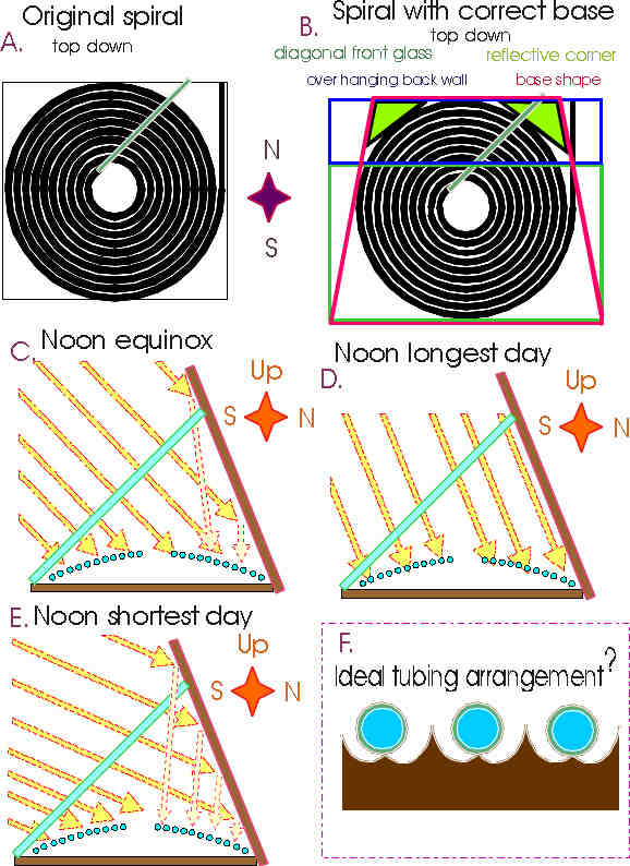
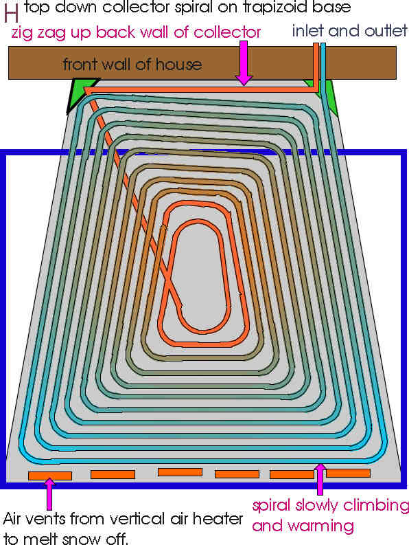
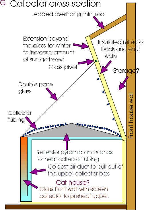
![[Thumbnail for collector.JPG]](/t/373670/a/290242/collector.JPG "Filename: collector.JPG
Description:")
![[Thumbnail for collector-box.JPG]](/t/373670/a/290243/collector-box.JPG "Filename: collector-box.JPG
Description:")
![[Thumbnail for collector-spiral.JPG]](/t/373670/a/290244/collector-spiral.JPG "Filename: collector-spiral.JPG
Description:")


![[Thumbnail for 20231206_144128_001.jpg]](/t/373670/a/291695/20231206_144128_001.jpg "Filename: 20231206_144128_001.jpg
Description:")