• Post Reply Bookmark Topic Watch Topic
  • New Topic
permaculture forums growies critters building homesteading energy monies kitchen purity ungarbage community wilderness fiber arts art permaculture artisans regional education skip experiences global resources cider press projects digital market permies.com pie forums private forums all forums
this forum made possible by our volunteer staff, including ...
master stewards:
  • Nancy Reading
  • Carla Burke
  • r ranson
  • John F Dean
  • paul wheaton
  • Pearl Sutton
stewards:
  • Jay Angler
  • Liv Smith
  • Leigh Tate
master gardeners:
  • Christopher Weeks
  • Timothy Norton
gardeners:
  • thomas rubino
  • Jeremy VanGelder
  • Maieshe Ljin

Water wheel hydro project Dorset

 
Posts: 4
6
  • Likes 2
  • Mark post as helpful
  • send pies
    Number of slices to send:
    Optional 'thank-you' note:
  • Quote
  • Report post to moderator
Hi Guys

I am new here!

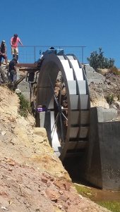
We are installing a new water wheel hydro electric scheme here at our family farm.

We have raised a lake and we now have 9 meters of head between our penstock pipe and our outlet pipe.  This is all installed and this summer we completed the reinforced concrete wheel pit construction so we are almost ready to install the wheel.

It will be 8.5 meters in diameter and 800mm wide.  I am led to believe should we get it fully operational it will be the largest electric generating water wheel in Europe.  In diameter at least!  Apparently the Aburdulais Wheel in Port Talbot, Wales currently holds this crown.

We have a flow of approximately 150 liters per second.  Almost all year round, slightly higher in the middle of winter and during heavy rain fall and slightly lower at the end of summer.

We have the wheel designed and is close to be able to be priced and fabricated.  It will be galvanised steel with a 100mm shaft, 72 buckets and big bearings etc.  Our aim is to have it built and installed by Spring 2023.

We are trying to size and source a gearbox and generator but we are struggling to calculate RPM of the wheel and horse power of the wheel.  So we are planning on simply installing the wheel and seeing how fast it goes round!  That will give us the RPM of course but we may have a little more difficulty deciding the horse power.

The gearbox looks easily obtainable.  A 3 stage planetary gear sets looks to be what we need and we can probably buy one almost off the shelf or be built to our requirements when we know them!  I believe it will need to gear up our wheel from what may be 4 or 5 rpm to 1200 or 1500rpm to turn the generator.

But the generator I am having more trouble sourcing a supplier.  So if anyone can recommend a generator fabricator/supplier in the UK I am really interested to speak to someone!

If anyone more qualified and intelligent than I, could help with working out the potential RPM, horsepower and potential KWH our wheel could generate I would be very grateful.

It has been very interesting looking at the other posts and comments on other systems on here.

TIA Brad.


pollinator
Posts: 5347
Location: Bendigo , Australia
477
plumbing earthworks bee building homestead greening the desert
  • Likes 3
  • Mark post as helpful
  • send pies
    Number of slices to send:
    Optional 'thank-you' note:
  • Quote
  • Report post to moderator
wow, its hard to comprehend you have got this far without the mechanicals sorted, well done.
All the info about the wheel can be done mathematically, I studied it at Civil Engineering school.
I cannot remember much, but the is a Hydro buff on this site, Thomas Rubino.
Hydro Engineers are the ones to help.
I will look around out of interest.
The head is 9m, Some questions;
- what type of wheel are you using, undershot, overshot or pelton?- efficiency
- What is the estimated flow rate?- determine power output
- What power output are you expecting? Kilowatts
- what is the ultimate use of the power, out of interest?
Once the expected power output is established, then a gearbox / generator can be obtained to match that output.
Photos would be nice, out of interest.
From; small town hydro power
Estimating power output
There is a simple equation you can use to estimate the power output for a system with 53 percent efficiency, which is representative of most small hydropower systems. Simply multiply net head (the
vertical distance available after subtracting losses from pipe friction) by flow (use U.S. gallons per minute) divided by 10.
That will give you the system’s output in watts (W).
The equation looks this: net head [(feet) x flow (gpm)]/10 = W.
IE approx 27 ft x 1000 us gal. x 0.1[ factor] = 2700 W.  the flow rate is critical to the equation.


Here is another source of info for others; https://www.renewablesfirst.co.uk/hydropower/hydropower-learning-centre/how-much-power-could-i-generate-from-a-hydro-turbine/
 
gardener
Posts: 2106
Location: Gulgong, NSW, Australia (Cold Zone 9B, Hot Zone 6) UTC +10
999
6
hugelkultur fungi chicken earthworks wofati food preservation cooking bee building solar rocket stoves
  • Likes 3
  • Mark post as helpful
  • send pies
    Number of slices to send:
    Optional 'thank-you' note:
  • Quote
  • Report post to moderator
Welcome to Permies Brad.  
Never wonder or worry that someone is more intelligent or clever than you.  We each have a skill set that makes Permies a highly intelligent family.
I am a nurse who managed to build a house so we can all do what we want with help and support, which is what your Permies family does best - help and support.
BTW our house is compressed earth bricks and completely off the electricity grid.

I would love to see photos of your work in progress.
Cheers
 
Brad Perrett
Posts: 4
6
  • Likes 2
  • Mark post as helpful
  • send pies
    Number of slices to send:
    Optional 'thank-you' note:
  • Quote
  • Report post to moderator

John C Daley wrote:wow, its hard to comprehend you have got this far without the mechanicals sorted, well done.
All the info about the wheel can be done mathematically, I studied it at Civil Engineering school.
I cannot remember much, but the is a Hydro buff on this site, Thomas Rubino.
Hydro Engineers are the ones to help.
I will look around out of interest.
The head is 9m, Some questions;
- what type of wheel are you using, undershot, overshot or pelton?- efficiency
- What is the estimated flow rate?- determine power output
- What power output are you expecting? Kilowatts
- what is the ultimate use of the power, out of interest?
Once the expected power output is established, then a gearbox / generator can be obtained to match that output.
Photos would be nice, out of interest.
From; small town hydro power
Estimating power output
There is a simple equation you can use to estimate the power output for a system with 53 percent efficiency, which is representative of most small hydropower systems. Simply multiply net head (the
vertical distance available after subtracting losses from pipe friction) by flow (use U.S. gallons per minute) divided by 10.
That will give you the system’s output in watts (W).
The equation looks this: net head [(feet) x flow (gpm)]/10 = W.
IE approx 27 ft x 1000 us gal. x 0.1[ factor] = 2700 W.  the flow rate is critical to the equation.

Hi John!

Thanks for the reply.  We are a ground works company and have worked on a few projects in the past installing hydro, wind and some very large solar projects for others so we have some snippets of Knowledge!

We are aware that a normal turbine may be more efficient.  However, this site with the lakes is out in front of my Father's house, and he is absolutely adamant he wanted a huge water wheel to look at going around for the rest of his days no matter what cost or efficiency implications it has!  So here we are, building the biggest wheel we can for him!  Of course we still want to generate the most electric we possibly can with the flow we have.

To answer your questions:

- what type of wheel are you using, undershot, overshot or pelton?- efficiency

We will be using a back shot or pitch back water wheel.

- What is the estimated flow rate?- determine power output

We have 150 liters per second we believe.  Less in summer.  But constant flow.  We assume we will generate 10-15 horse power at a bit of a guess so far.

- What power output are you expecting? Kilowatts

I really have no idea yet!  

- what is the ultimate use of the power, out of interest?

We have a farm here, with about 20 commercial industrial units, 5 houses and various stable blocks etc.  We are hoping the electric we generate will contribute to our use.  

I have attached a couple of PDF plans just for your interest.  They are only basic and not 100% as built just yet.  But close!  And some pictures of our finished concrete wheel pit,  It needs some landscaping in Spring!  But we have just began a very wet winter period!

Thanks Brad

Filename: HYDRO-ELECTRIC-POWER-SCHEME-COURT-FARM-BUCKLAND-NEWTON-CF003.pdf
File size: 524 Kbytes
Filename: WATERWHEEL-DETAIL.pdf
File size: 44 Kbytes
IMG_7024.jpg
[Thumbnail for IMG_7024.jpg]
IMG_7025.jpg
[Thumbnail for IMG_7025.jpg]
IMG_7026.jpg
[Thumbnail for IMG_7026.jpg]
IMG_7027.jpg
[Thumbnail for IMG_7027.jpg]
IMG_7028.jpg
[Thumbnail for IMG_7028.jpg]
 
Brad Perrett
Posts: 4
6
  • Likes 3
  • Mark post as helpful
  • send pies
    Number of slices to send:
    Optional 'thank-you' note:
  • Quote
  • Report post to moderator

Paul Fookes wrote:Welcome to Permies Brad.  
Never wonder or worry that someone is more intelligent or clever than you.  We each have a skill set that makes Permies a highly intelligent family.
I am a nurse who managed to build a house so we can all do what we want with help and support, which is what your Permies family does best - help and support.
BTW our house is compressed earth bricks and completely off the electricity grid.

I would love to see photos of your work in progress.
Cheers


Thanks!  That sounds awesome, my partner is also a nurse!  A very good one, but she hasn't built a house yet!

I have attached some drawings of our set up here, we have a chain of 4 lakes.  Between the 3rd and final lake we raised the lower lake bank of considerably, so we have a head of 9 metres between the water level of the 3rd lake and the water level of the 4th lake.  It is more than that actually but we have 9 metres left when you account for the fall on the pipes.  9 metres from inlet of penstock tube to wheel pit to outlet pipe the other end of the wheel pit.

I have attached a drawing of a basic wheel size and design above but this is limited and we already nearly have a full 3D model of the wheel as it could be fabricated, so we are making head way.  The bucket design and spokes and everything is getting more and more accurate.  The wheel will be fabricated in 4 sections so it can be re built on site by bolting together with no welding required.

Then I have attached some pictures of the wheel pit as it is now, ready for a wheel, it just needs bearings that we have specified and ready to buy.  

There will be a plant house/room built to the left of the wheel pit in brick and a slate roof all to look nice to house the gearbox, generator etc and all electric control boxes with a door to get in so access is all easy.  Then all nice railings and
landscaping and paths around it so it can be seen and viewed safely and easily.

There will no doubt need to be some electronic level and sluice gate control systems down the line to regulate flow, especially in the summer perhaps but we will worry about that when we get further along.

There is still a lot we don't know, but the closer we get the more exciting it gets!  It will look cool hammering around, if it actually ever generates some electric, it's a bonus!

Brad

Filename: WATER-WHEEL-3D-CAD-DESIGN.pdf
File size: 214 Kbytes
 
Paul Fookes
gardener
Posts: 2106
Location: Gulgong, NSW, Australia (Cold Zone 9B, Hot Zone 6) UTC +10
999
6
hugelkultur fungi chicken earthworks wofati food preservation cooking bee building solar rocket stoves
  • Mark post as helpful
  • send pies
    Number of slices to send:
    Optional 'thank-you' note:
  • Quote
  • Report post to moderator
With the wheel, it looks like there will need to be a very big gear to get the required RPM for generation.  Would a pelton wheel work? With the head you describe and a reducing nozzle you may have enough water pressure to drive a 2Kw wheel.  Then it is a matter of a straight conversion to a 3 phase motor and rectifying it to put into batteries.  If you use undershot or vertical axis, this increases the available head.

I am not sure of the fluid pressure but someone like John will know.
 
John C Daley
pollinator
Posts: 5347
Location: Bendigo , Australia
477
plumbing earthworks bee building homestead greening the desert
  • Likes 3
  • Mark post as helpful
  • send pies
    Number of slices to send:
    Optional 'thank-you' note:
  • Quote
  • Report post to moderator
Brett it looks good.
From ;https://www.backwoodshome.com/design-calculations-for-no-head-low-head-waterwheels/
wheel design
Use wood bearings
I recommend oil-impregnated wood bearings.
They can be obtained from the POBCO Bearing Company of Worcester, MA.
Waterwheels turn too slowly for ball or sleeve bearings; they cannot maintain a uniform lubricant field.
This tends to ruin the bearing quickly.
The wood bearings have a “wick” action that maintains uniform lubricant.
Next issue, we will adapt these equations to overshot wheels and get into the economics of going into the co-generation business.
 
John C Daley
pollinator
Posts: 5347
Location: Bendigo , Australia
477
plumbing earthworks bee building homestead greening the desert
  • Likes 2
  • Mark post as helpful
  • send pies
    Number of slices to send:
    Optional 'thank-you' note:
  • Quote
  • Report post to moderator
Power expected
From ; https://sciencing.com/calculate-water-wheel-power-7604567.html
"The flow rate is the volume of water moving onto the water wheel per unit time.
This is usually measured in liters per second, cubic meters per second or cubic feet per second.
Multiply the net head distance in meters times the flow rate in liters per second times 9.81, which is the acceleration due to gravity, measured in meters per second.
This calculates the hydro power in watts.
As an example, If the net head was 20 meters with a flow rate of 25 liters per second, then the hydro power would be 20 times 25 times 9.81, or 4,905 watts."

Now in your case , flow is 150 L /sec. the head is 4M
Sp 150 times 4m times 9.81 =5886W
Allow 70% efficiency. Expected power = 4120w or 4.12 Kw

 
Brad Perrett
Posts: 4
6
  • Likes 3
  • Mark post as helpful
  • send pies
    Number of slices to send:
    Optional 'thank-you' note:
  • Quote
  • Report post to moderator
Thank you for the further replies.  We think we need a traditional back shot wheel in our layout and circumstances.  The power calculations have been very helpful!  And the bearing recommendations we will look in to!

We have found someone in this country reasonably local that has installed a wheel already that is working and we are able to visit it and pick their brains.  And hopefully a consultant and now a generator supply company that can deal with the generator and control and flow control systems.  We have some gearbox companies that should be able to be the middle man between water wheel and generator.

We are approaching a more finalised wheel design.  I will post it when completed.

Brad

 
Is that almond roca? Did you find it in the cat box? What is on this tiny ad?
2024 Permaculture Adventure Bundle
https://permies.com/w/bundle
reply
    Bookmark Topic Watch Topic
  • New Topic