• Post Reply Bookmark Topic Watch Topic
  • New Topic
permaculture forums growies critters building homesteading energy monies kitchen purity ungarbage community wilderness fiber arts art permaculture artisans regional education skip experiences global resources cider press projects digital market permies.com pie forums private forums all forums
this forum made possible by our volunteer staff, including ...
master stewards:
  • Carla Burke
  • Anne Miller
  • Nancy Reading
  • John F Dean
  • r ransom
  • paul wheaton
  • Timothy Norton
stewards:
  • Jay Angler
  • Pearl Sutton
  • Andrés Bernal
master gardeners:
  • Christopher Weeks
gardeners:
  • M Ljin
  • Thekla McDaniels
  • May Lotito

My small solar DC only build

 
Posts: 205
Location: Chicago suburbs (until I can fix that part...)
44
dog plumbing wofati cooking building solar
  • Likes 11
  • Mark post as helpful
  • send pies
    Number of slices to send:
    Optional 'thank-you' note:
  • Quote
  • Report post to moderator
First of all, I wish to apologize to the volunteer reviewer staff that I subjected my initial BB to, as it was a truly sloppy submission & I both know better, and can/should do better.  As I shall illustrate here:

Next, the disclaimers - electricity can be dangerous and so can stored energy systems, ie. batteries, so be careful, and if there's something/anything that is unclear, get help!  This is NOT a how-to guide, but rather a "How I did" journal. Use your best judgment on how to proceed with your own projects. Neither I or this site bear any responsibility for your actions, for better or worse. Best of luck with your own builds!

This set of batteries can pack a lot of energy in a small space:
314 Ah cells in a 4S configuration = 314 amps x 3.2 volts x 4 cells, which equals 4019.2 watt-hours, or 4 Kwh. Even if they were 100 Ah cells, it would still be a KWh of energy, so be careful with yours, no matter what size you use!

This thread is to showcase what I ended up using, not necessarily what I started with, as there was certainly learning along the way. As I also am building a larger system along with this one, some of the components are the same as used in both, and some components were simply purchased at the same time/arrived in the same Amazon box, etc., I will try to notate when it's unclear which parts are for which systems, but for example, Anderson SB connectors have a color code, which I will follow as close as I can, so red ones are for 24 Vdc connections, yellow ones are for 12 Vdc connections, and black ones are for officially 72 Vdc connections, although I will stick to using black for solar input connections of any voltage, to make them incompatible with either of the lower voltage ones (for safety).

Having said that, I did skip the permanent connections initially, for testing, but I fully intend to get there, and it will be pretty when done!
The same can be said of circuit breakers, but skipping those, is starting to gamble with some higher stakes... Please use common sense on that!

Starting with the batteries, or rather, the cells:
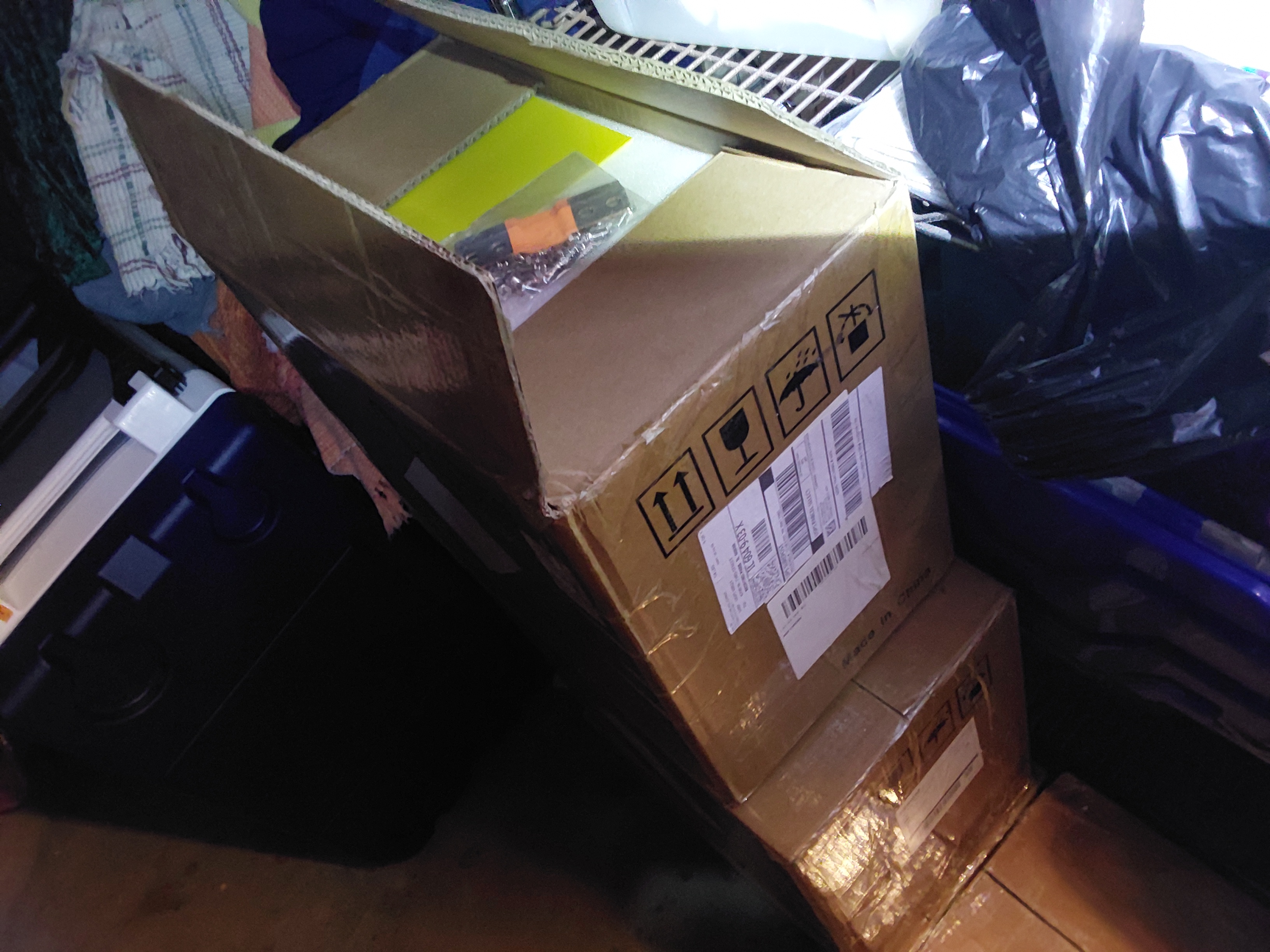
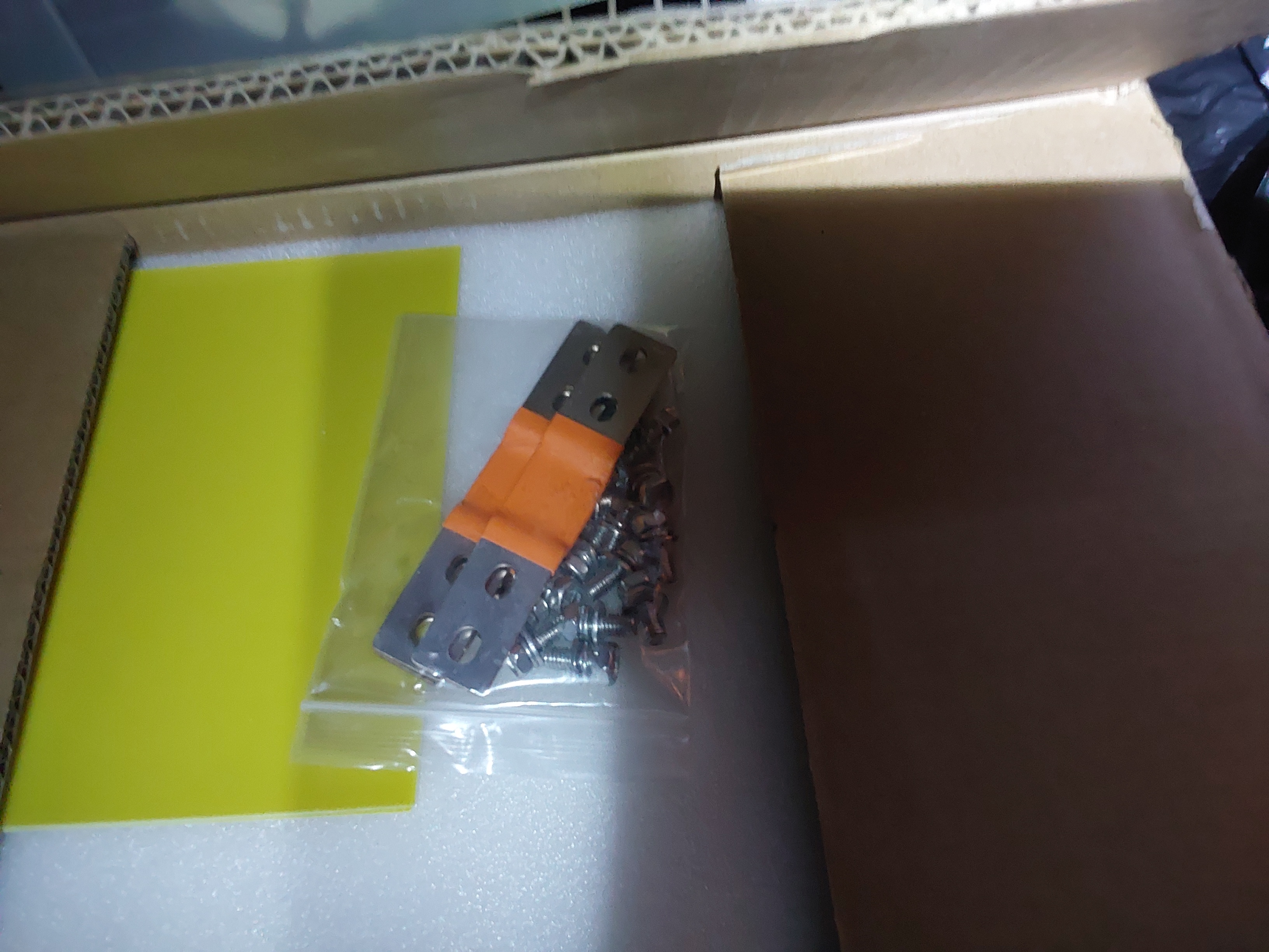
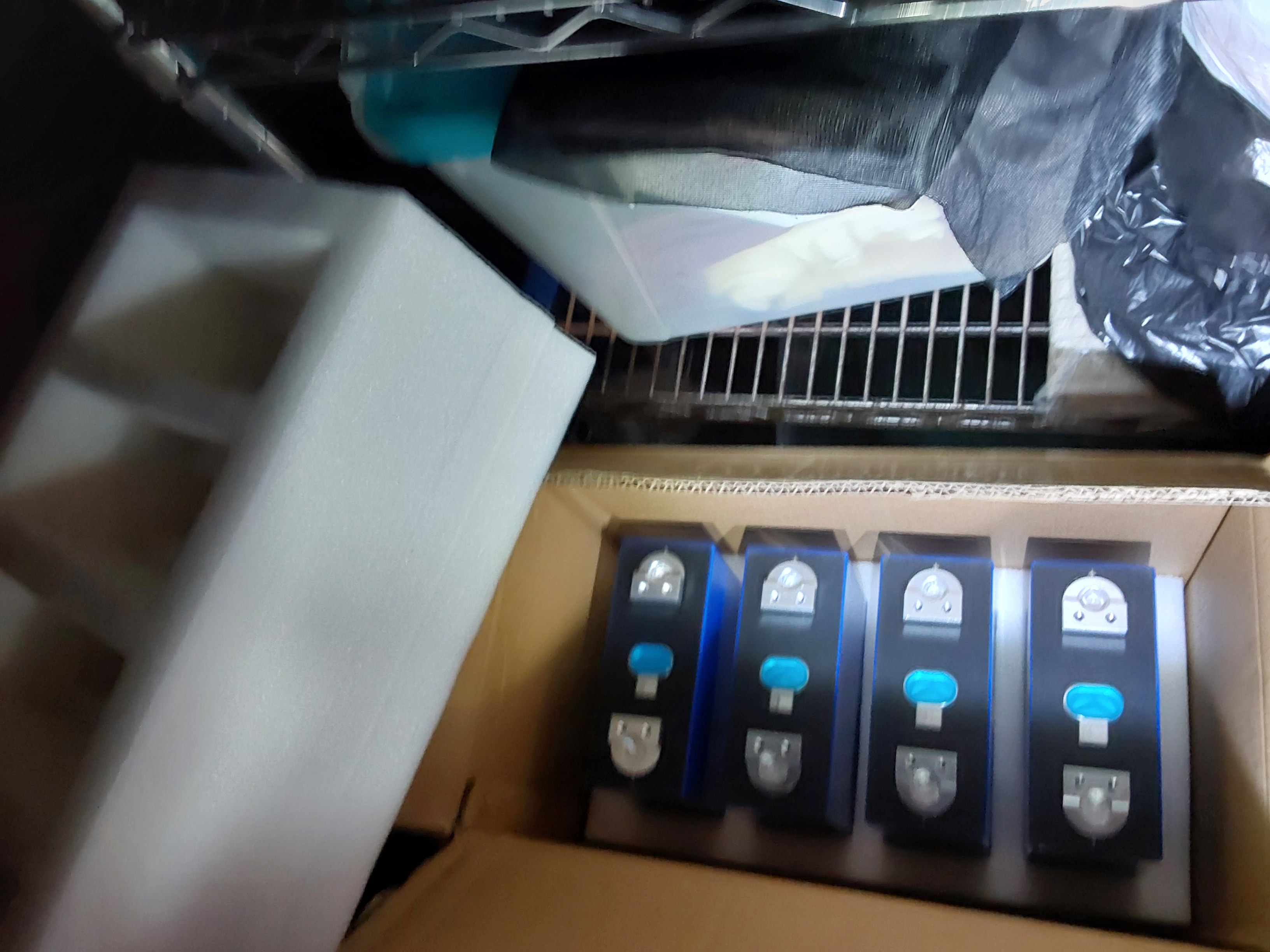
These are the commonly available EVE MB31 cells. I bought mine directly from a Chinese vendor in a bulk purchase. The specific cells I used in this build came from the factory with double M6 terminals. These pictures are not the exact ones that I used in the 12 Vdc build - I didn't take pictures of the unboxing of those, but these are the exact same model cells - I bought 80 of them for personal use at the time...

1000015676.jpg
[Thumbnail for 1000015676.jpg]
1000015677.jpg
[Thumbnail for 1000015677.jpg]
1000015678.jpg
[Thumbnail for 1000015678.jpg]
 
Allen Jackson
Posts: 205
Location: Chicago suburbs (until I can fix that part...)
44
dog plumbing wofati cooking building solar
  • Likes 10
  • Mark post as helpful
  • send pies
    Number of slices to send:
    Optional 'thank-you' note:
  • Quote
  • Report post to moderator
Logically, the next step is to show the container I used to build it in. I ended up using a cheap plastic toolbox from Harbor Freight, that came as the outer box of a nested set of 4 toolboxes. It works so far, but it's less than ideal, because the latches & hinges are the weak points, and this will probably be over 60 lbs when done.
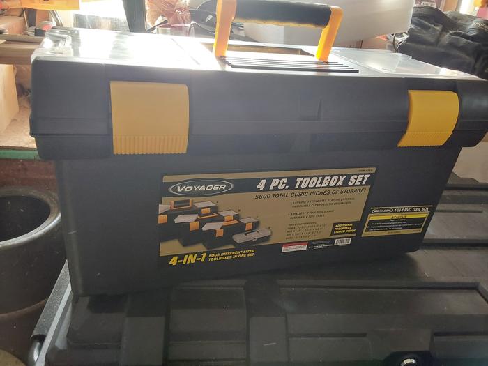


I initially tried putting the batteries at one end.
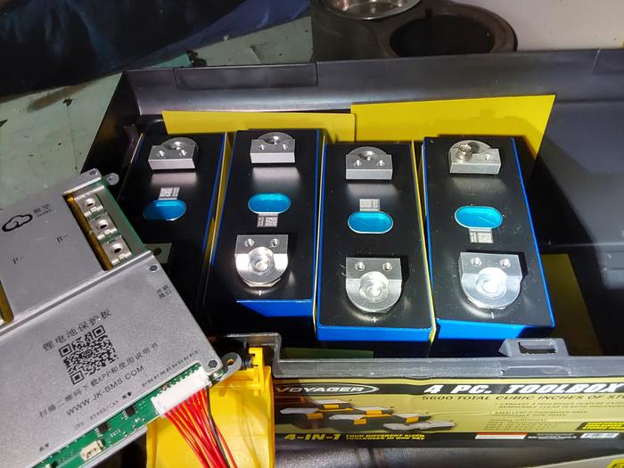


That proved to be too imbalanced to carry with the handle, so they were moved to the center and blocked with some of the close-cell foam packaging they arrived with...
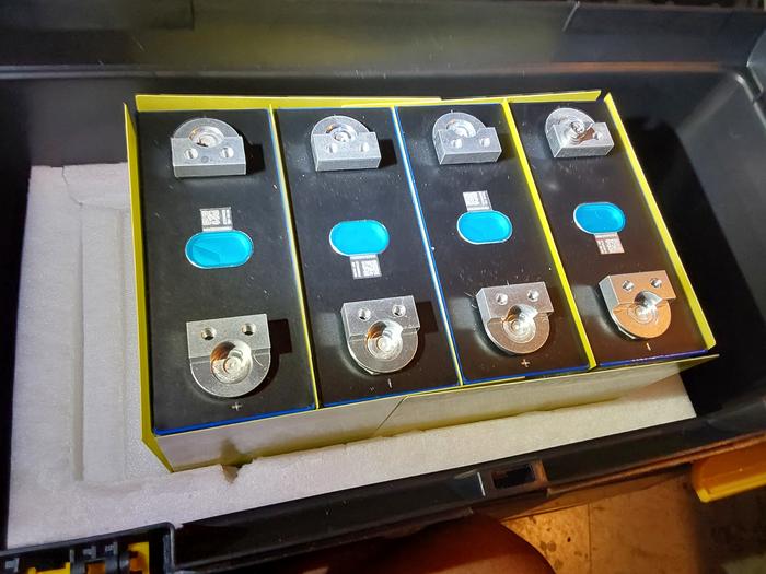


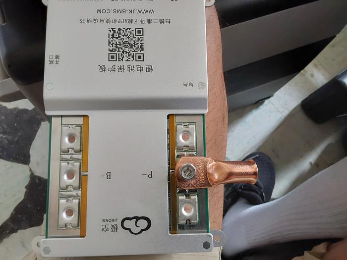
Moving into this box was also in conjunction with switching to a much higher capacity BMS, shown here:


And connecting the balancing/cell sensing wires:
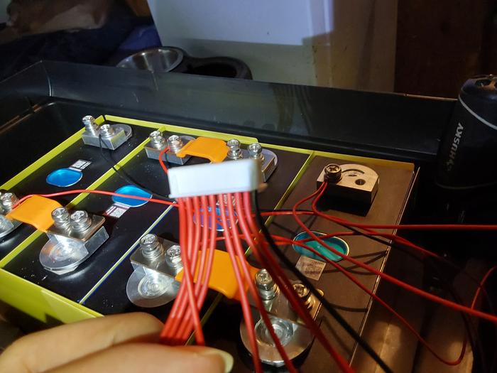


The unused wires can just be coiled up and taped out of the way.
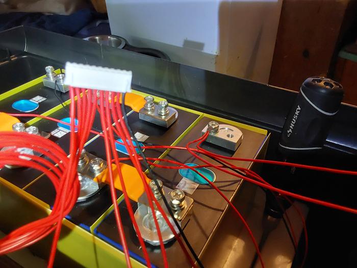


A 300 Amp BMS should have a 300 amp-capable wiring harness and connections! As I'm really not intending to need or use that much raw current, I'll wire for 200 amps, & fuse for less than that. The recommended max normal charging rate is 157 amps for this battery pack, so I can do at least that...

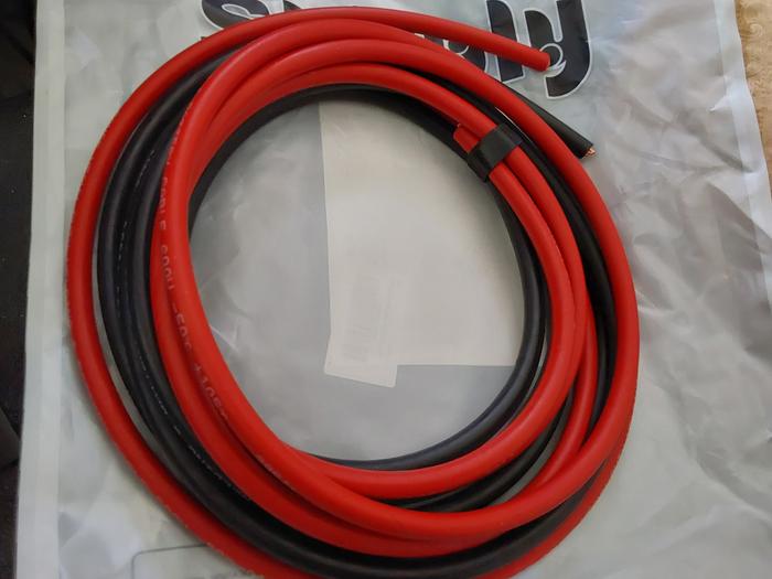
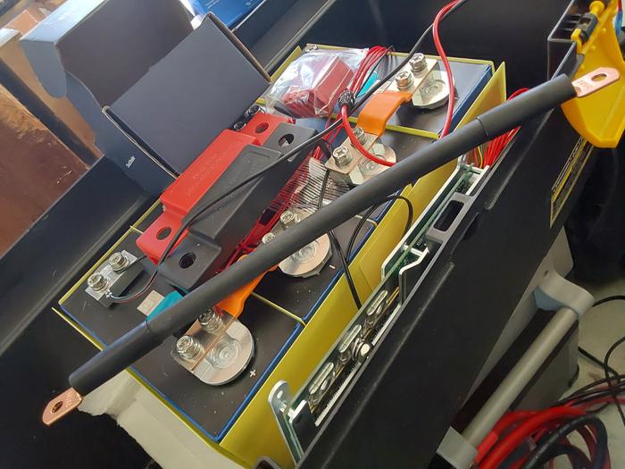
This 2/0 welding cable is rated for over 200 amps, so it should be sufficient, and I have adequate crimps to put on the ends.
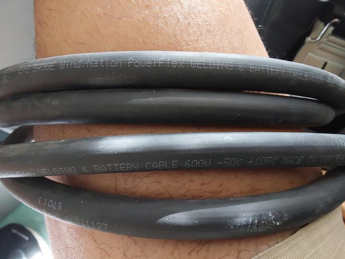


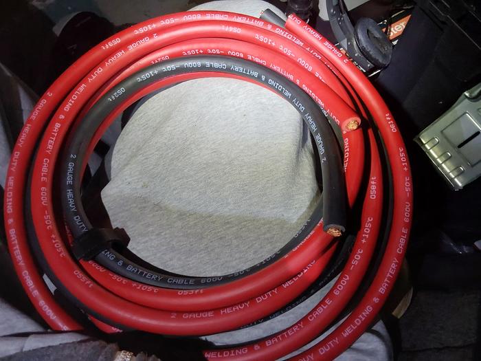
But since I really don't expect to have reason to push the 150 amp breaker, I'll use this 2 gage cable - it's much easier to bend, and this welding cable has pretty high temp insulation (105 C), so it should be good for up to 215 amps.


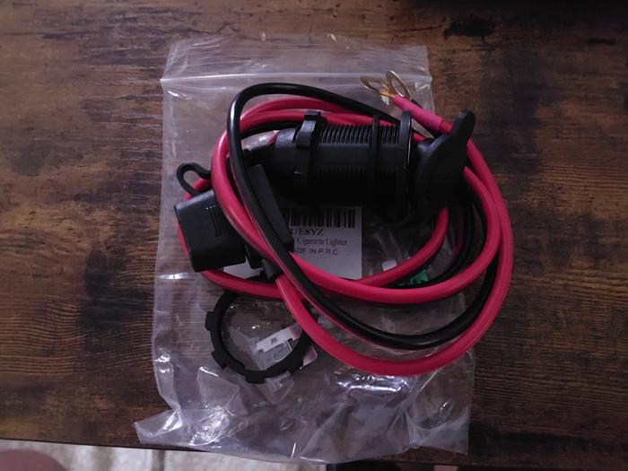
My initial mockup included 12 Vdc outlets with USB charging ports, to charge my tablet and mp3 player while working on wiring the BMS and the rest of the system, but I found out the really cheap fuse holders for the USB outlets started melting (without blowing the fuse!, so I scrambled for a heavier duty fuse and wiring harness for them.
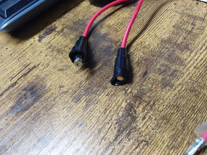


Very heavy-duty 12 Vdc socket, with a 20 amp fuse and 12 gage wire


Public service announcement:
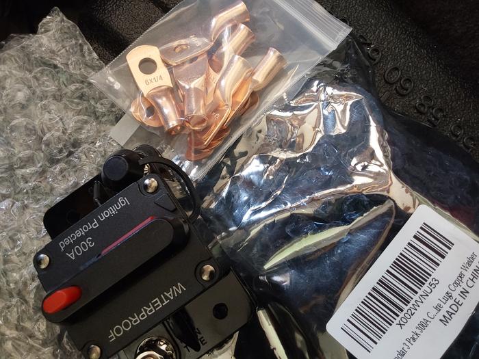
If you are ever tempted to buy & use these cheap breakers from Amazon, under NO circumstances, should you be using 6 AWG wire that these terminal lugs are sized for - if you do, your wire will burn up long before you EVER get to 300 amps.!  Use large enough wire to carry 300 amps, or use a smaller breaker rated to protect the size wire you actually are using...


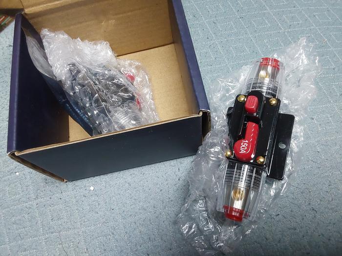
This is a much better design for a heavy duty breaker, but I didn't find it soon enough to replace the other one (yet)
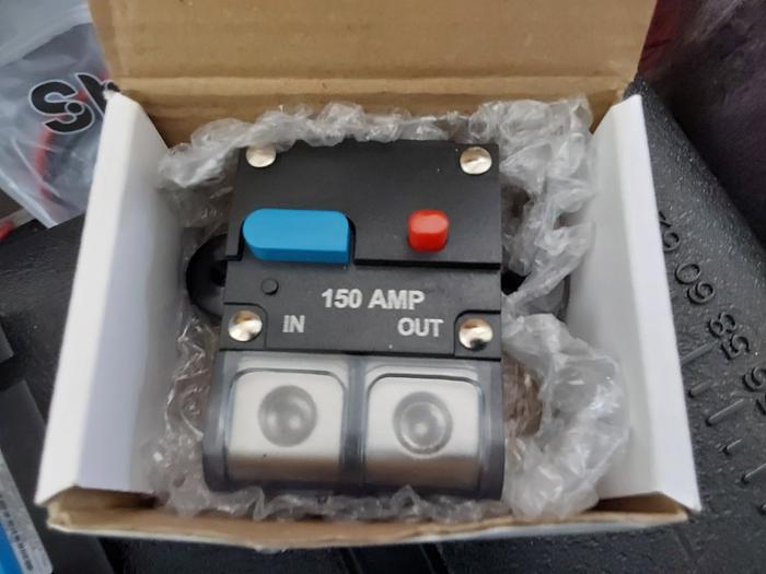


These are what I'm trying to use, but their ports aren't really large enough to support the large enough wire to match their rating without a lot of work & modification.

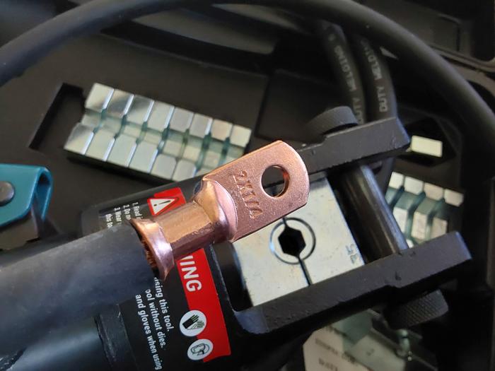
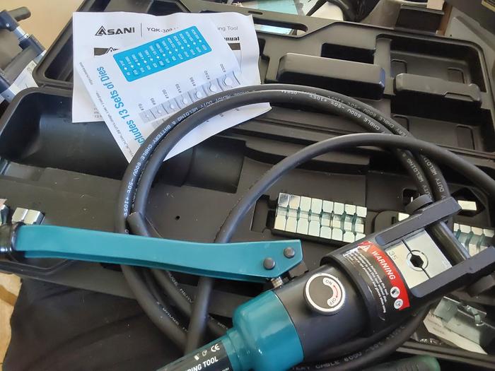
Working with larger crimps requires bigger tools:
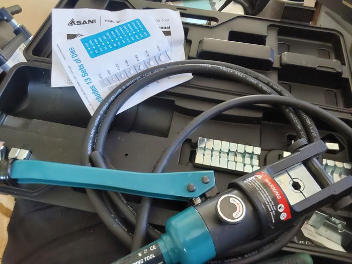


The struggle to fit it is in this post:  https://permies.com/t/120/274663#3772120

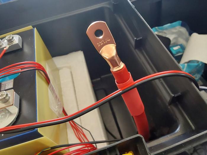
It's a good idea to put heatshrink tubing on the ends, but don't cover up the flats of the lugs, for best contact.


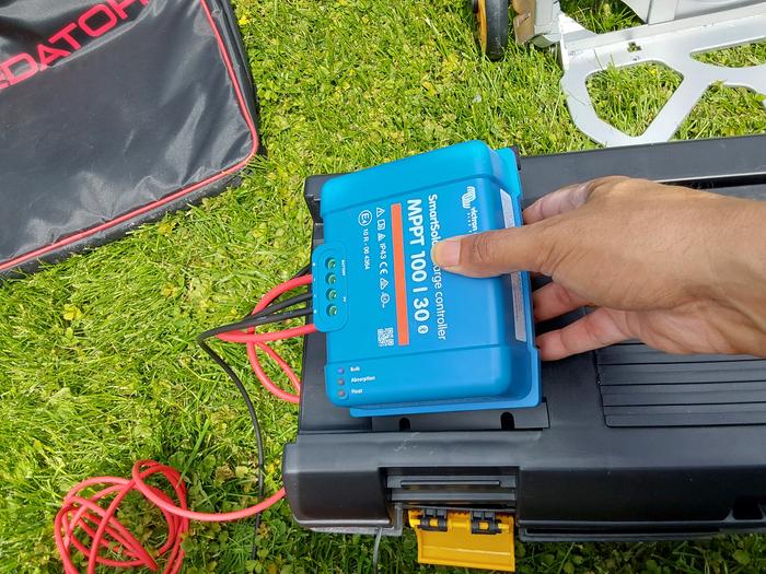
This is one of the solar charge controllers in the system (one of 3), and it's the one I started with:
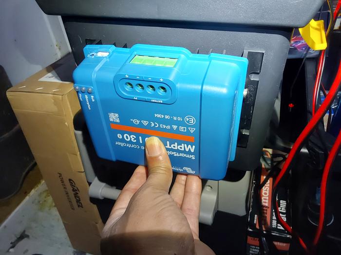


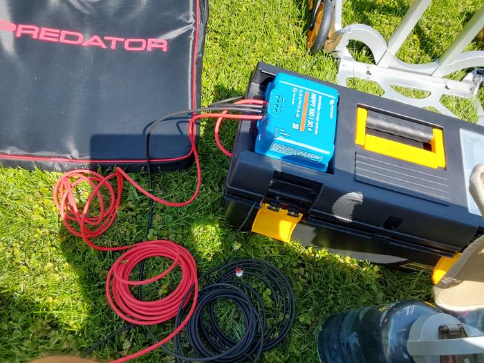
Testing a mockup in the back yard, showed that it didn't generate enough heat to worry about additional ventilation, so it's ended up inside the box now.


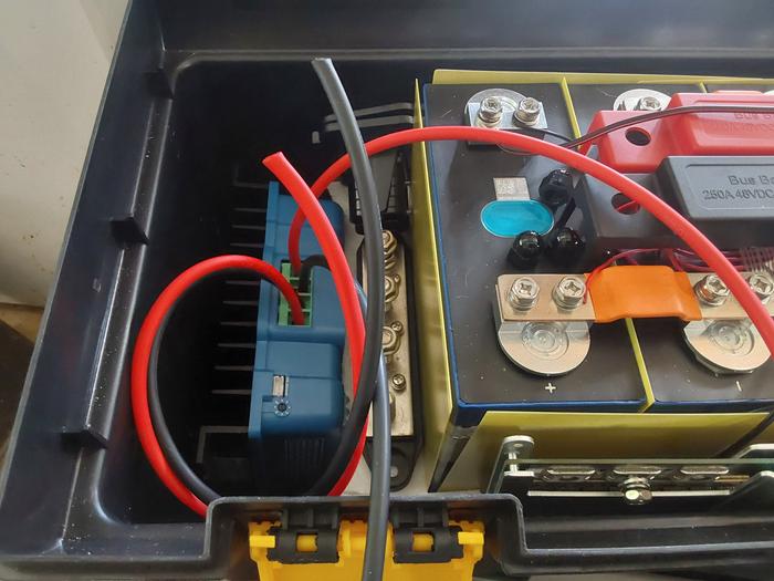
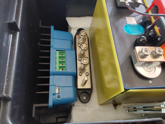
The negative bus bar is shown here too, prior to connecting anything to it.  The left edge of the 300 amp BMS is toward the bottom right & mostly out of the frame here.


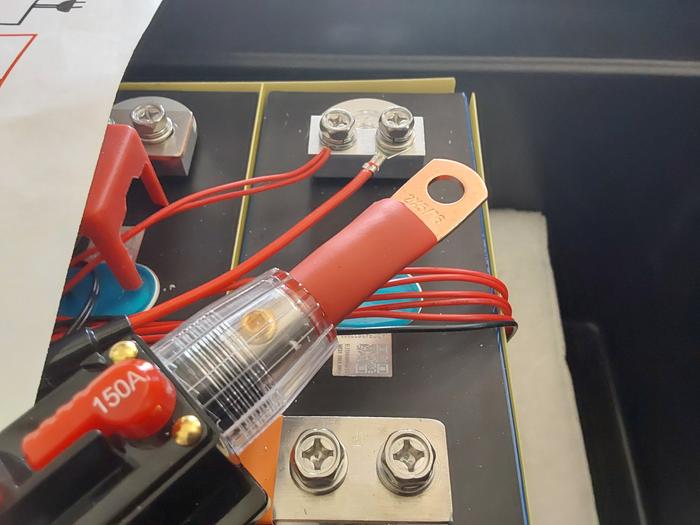
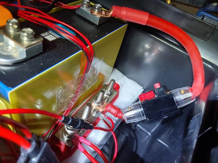
Here's a glimpse of the positive bus bar, with the 150 amp inline breaker and the 2 AWG copper cable connecting to the main battery positive post:


The 100|30 amp Victron in it's final home, working just fine:
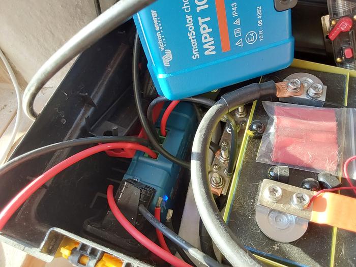


I used 10 gage PV wire for the battery and PV sides of the 30 amp controller because neither of them will ever see more than 30 amps, although the mfg still recommends putting a 40 amp breaker on the battery side and some kind of DC-rated disconnect on the PV terminals too... I skipped that for now, but I'll get there eventually?

This is where & what I used for the initial 10 gage PV wire - I just cut off sections of the raw ends as needed to make the shorter connections and saved the rest for connecting to the solar panels later:  10 gage PV wire from Amazon

The top right corner shows the original parts before chopping the cable up, and the bus bars are also in this collage too.
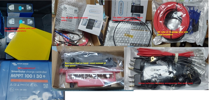
(what's left of the 2 rolls is laying on the toolbox below the pouch that holds a multimeter)
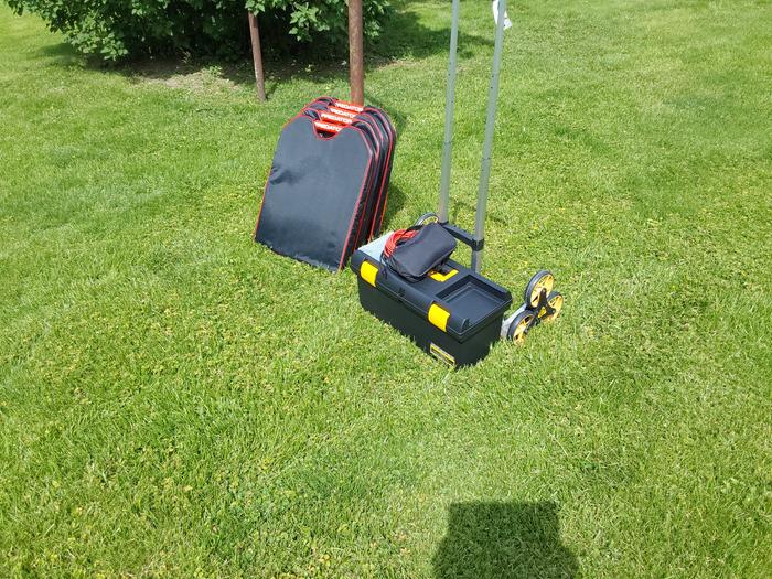
And temporarily connected here:


The 40 amp inline breaker is visible on the far right side of this collage, and the lower left corner shows the USB outlets (which are truly awesome, but don't use the stock wiring that they come with, it will melt...
Best to put spade lugs on your own 12 gage wire with a 20 amp inline fuse...
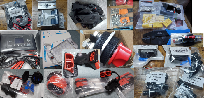


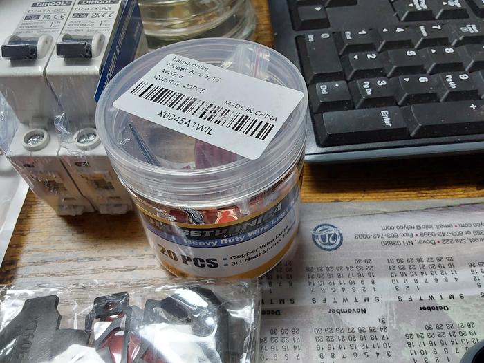
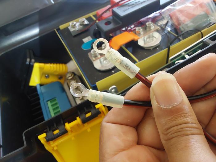
I also replaced the ring terminals on the ends, with smaller ones, because there's no way those wires needed to be connected to a 5/16" lug on the bus bar...

I've added a few more controllers, but they are the 100|50 amp variant
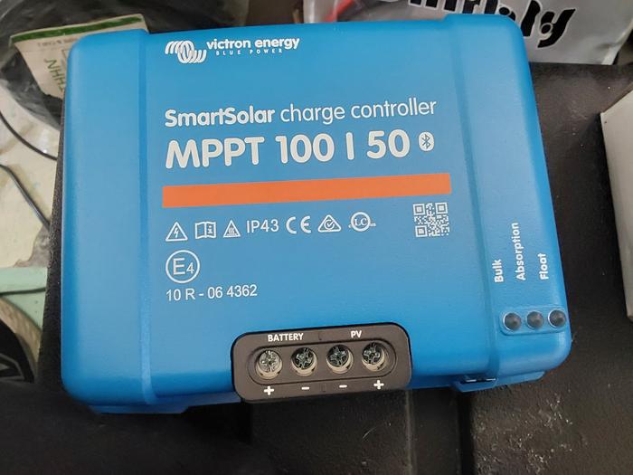


The 6 gage terminal lugs I ended up using on the 6 gage wire, when needed (for 50-amp connections to the bus bars from the 50-amp controllers):


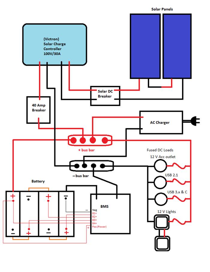
BTW, this is the basic schematic I'm following for this build - although I have more than one charge controller they always connect in parallel), and initially, I've skipped the circuit protection on solar side. I DID include a main breaker on the battery positive connection (not shown in the schematic), though!


The AC charger has clamps, and I'm debating whether I want a permanent dedicated socket for it or not... Maybe a combo port for the AC charger OR a vehicle charger connection???

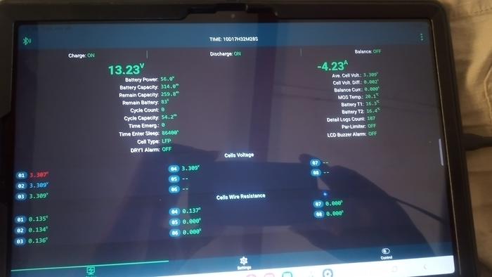
Here's a glimpse of the BMS screen, showing the function.


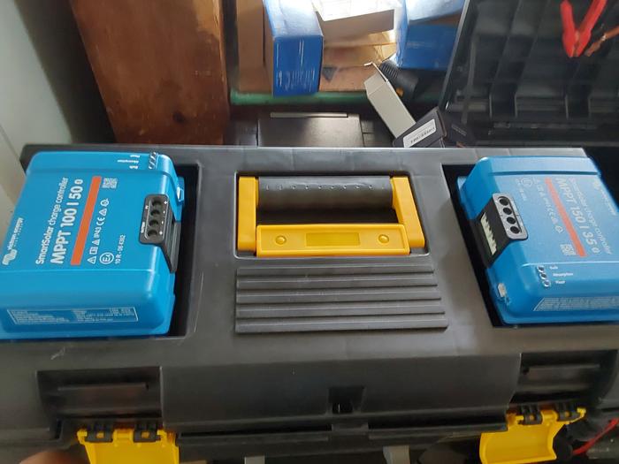
The 30 amp charge controller is way too small in capacity for my patience and my luck, as it can only charge a 12 Vdc system at a max rate of just over 410 watts in my real-world testing. For a 4 KWh battery, that would require about 10 hours of GOOD sunlight to recharge from empty, and the charge current of 30 amps or so, is far below the recommended max normal charge current of 0.5 C, which is 157 amps for this pack. I can and should strive to do better. I opted to switch to a pair of the 100|50 amp charge controllers that the top of the box, because they seemed to fit really well up there; I'll pull out the 150|35 amp controller and save it for a higher voltage project.


I've gone back and forth about the placement of the bus bars, but I realized that putting them on their sides at the bottom, would save space, but make them inaccessible, so that wouldn't work out well. I've split them up with positive and negative on opposite ends of the battery, which makes it a lot safer to work on too.  After the bus bars are placed, the rest of the placement is easy and mostly falls into place, since the wiring for everything else is much more flexible than the main bus bar feeders are.

The positive cable was more of a challenge because of the need/desire to put a breaker on it.
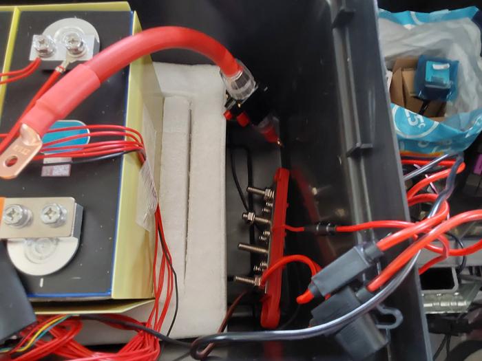

The most space-efficient place to put this is deep down here, but there's no tool access to connect anything else later!
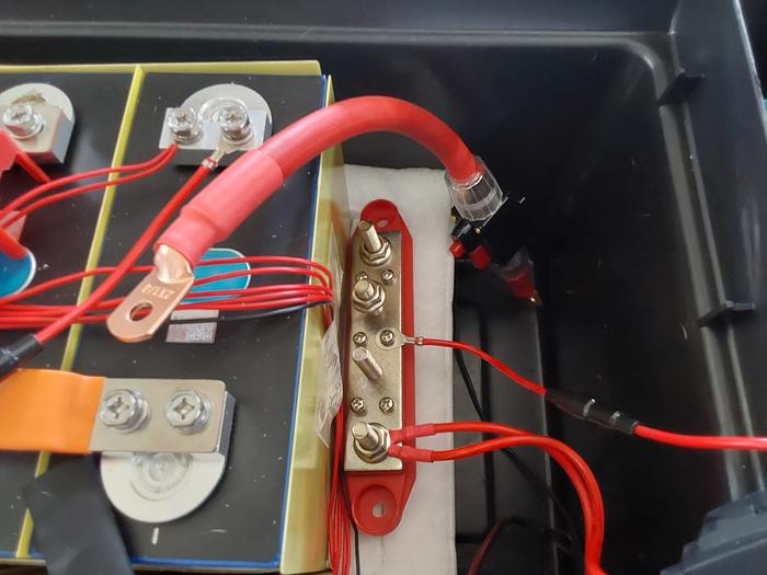

These look like better options for general access and use, but getting the positive cable attached?!?


The negative side has far less drama...


Where the positive cable has landed. I cut off the insulation and just used heatshrink to get more bend.
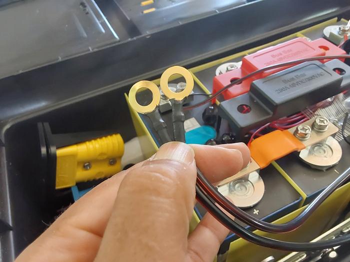

We can do better than this - we have additional M4 connection points!
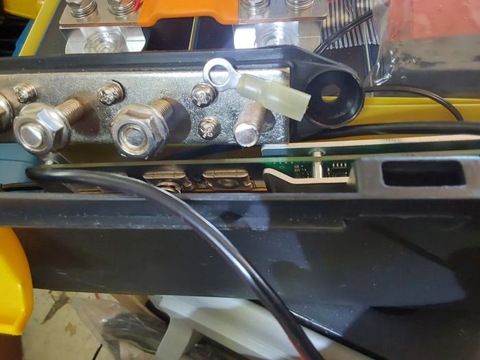

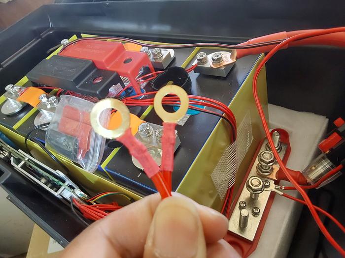
Have crimp, will travel?

For the negative side

And for the positive side too
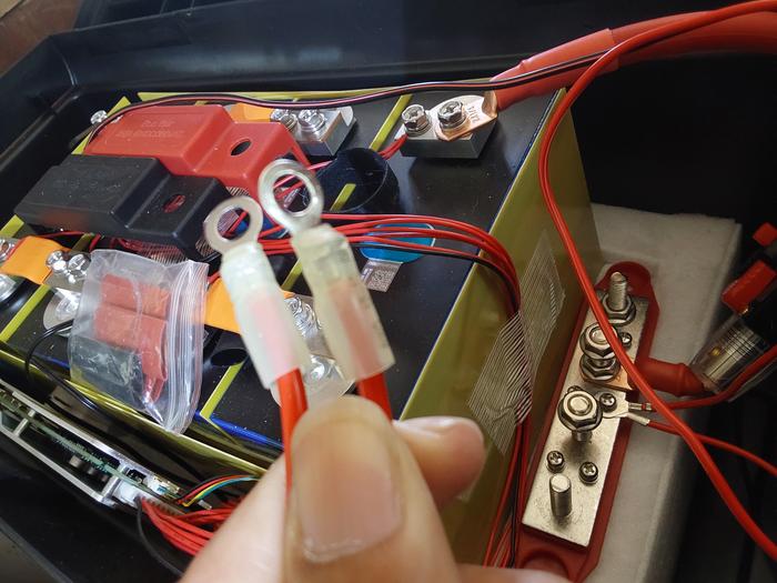

Now both can easily attach to the M4 screws on the bus bars

I have one more placement challenge - if I were to ever want to use this box with an inverter, where I put that connector?!? If I put it on the end where the 3rd charge controller is sitting, it will interfere with pulling it out and I'll need to wire it in place before covering it up (the block of wood with the DIN rail breakers is slated to go over the negative bus bar).

The positive end of the box will be cluttered up with the other load connections and switches, so that's still a challenge.

I currently only have 4 of the black SB50 connectors, and if I'm going to actually use them for the solar/high-voltage inputs, I'll need 3 on the box for the 3 charge controllers, and 3 more for the cable harnesses to connect each to its own solar array, so I'll order more...
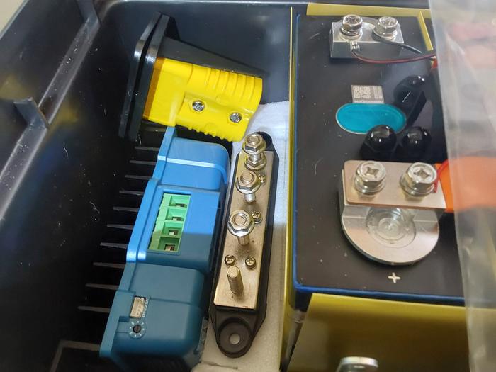

Anderson SB175 panel mount connector here - for either battery expansion or an inverter - will block removal of the controller
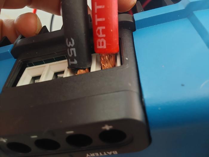

Wiring up the 50 amp controller - THIS IS A HORRIBLE PLACE TO GET STRAY WHISKERS! DON'T!
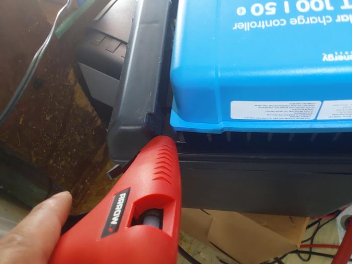

I found a hot glue gun!
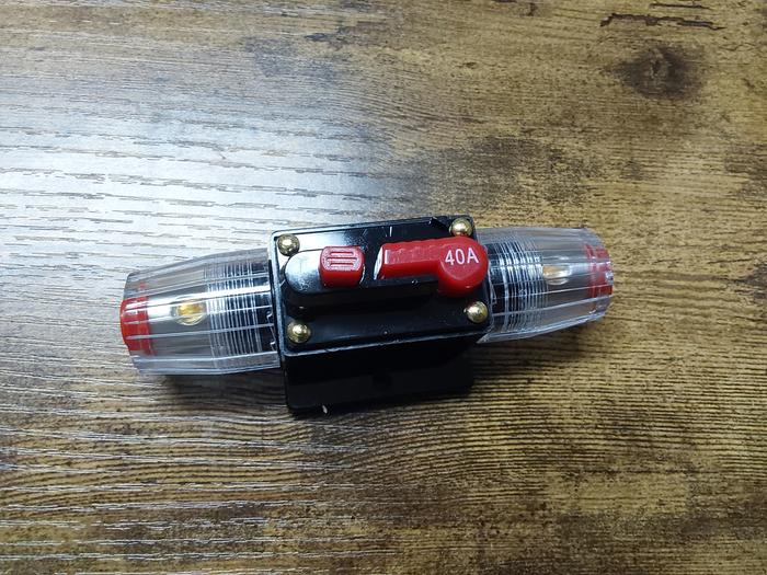

I bought several variants of this breaker, from 40 amps up to 150 amps

The 60 amp version is a reasonable fit for the top-mounted controllers, and these terminals actually will fit 6 gage wire just fine.
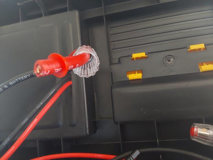
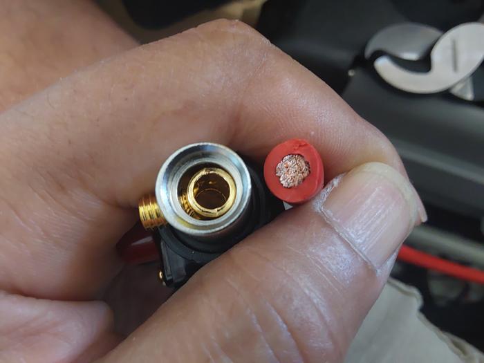


it looks like a tight fit, but it worked, including the ferrule and the weather seal
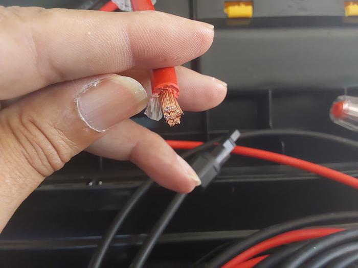

When stripping wire, make sure there's no extra plastic left
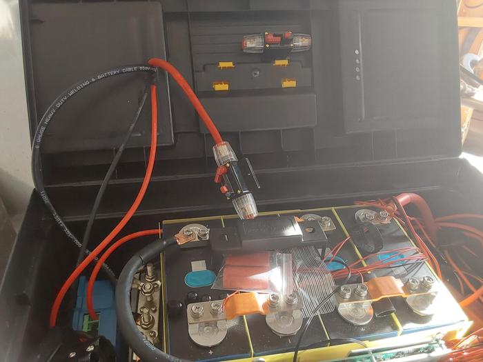

It will fit, and there's enough play to open/close the lid too, with both 60-amp breakers under the lid.

I plan to hot glue the breakers in place, but I want to get both of them wired and make sure I can close the lid first.

This is also about as far as I had gotten with the mounting of everything, although I still should put holes in the box, to allow all the panel mounted items to be, well, panel mounted... And then the trip to Wheaton Labs happened, and it got packed up and carried across the country, while running a refrigerator and freezer, and recharging our other devices too.

It wasn't real pretty with the lid propped open to access the cables, and I forgot to pack the Allen wrench to tighten the connector on the 60 amp breakers, plus the other PV cables too, but it worked well enough to get us through the week! (And it technically does meet the requirements for the badge bit, as is, but it's certainly not the best version of itself yet).

I ended up finding a local solar dealer who would sell me some PV cable, so I was able to hook up 2 of the 3 controllers and 800 watts of panels. They seemed to max out at just over 600 watts total in the best of sun, but I don't promise that the panels were perfectly aimed, either.  It was certainly good enough for this trip.

 
Posts: 4
Location: Perth WA, Australia
1
  • Likes 9
  • Mark post as helpful
  • send pies
    Number of slices to send:
    Optional 'thank-you' note:
  • Quote
  • Report post to moderator
Nice build, and thanks for the detailed write-up. A few things from my experience with 4S LiFePO4 boxes of this size that might be worth a look before you close it up:

1. Short-circuit protection. A 314 Ah 4S pack can deliver well over 10,000 A into a dead short, and the BMS MOSFETs will not reliably save you from that. Many breakers and ANL or MRBF fuses are only rated to interrupt around 2 to 6 kA at DC. For the main battery lead, a Class T fuse (rated 20 kA or more) mounted as close to the positive terminal as practical is the usual answer. Size it to protect the wire, not the loads.
2. DC breakers must be DC-rated for the voltage, and polarity-sensitive ones must be wired the right way round. The 60 A breakers on the charge controller inputs are fine, but check the datasheet voltage rating against your PV array's open-circuit voltage in cold weather (Voc rises about 0.3 percent per degree C below 25 C).
3. Cell compression. EVE 314 Ah prismatic cells last noticeably longer with light, even compression (roughly 300 kgf for the pack is the common figure). A rigid fixture or end plates with a thin foam layer is better than loose foam blocks if the box will be carried around.
4. Terminal torque and bus bars. Torque the M6 terminals to the cell maker's spec (around 4 to 6 N·m) and recheck after the first few thermal cycles, since loose terminals are a common source of heat. Use clean, flat bus bars with a bit of anti-oxidant paste, particularly where aluminium meets copper.
5. Charging. Set the charge controllers to about 14.2 to 14.4 V absorption with a short absorption time, float around 13.5 V or off, and temperature compensation turned off for lithium. Don't charge below 0 C unless the BMS has a low-temperature cutoff, because lithium plating is permanent.
6. Cabling in a carried box. Secure the heavy cables so they can't pull on the lugs while you carry it, and use ferrules or properly crimped lugs only.

My position is that the fuse is the item people most often skip, so I'd put that first on your list.
 
Allen Jackson
Posts: 205
Location: Chicago suburbs (until I can fix that part...)
44
dog plumbing wofati cooking building solar
  • Likes 6
  • Mark post as helpful
  • send pies
    Number of slices to send:
    Optional 'thank-you' note:
  • Quote
  • Report post to moderator

Chandrapal Mehula wrote:Nice build, and thanks for the detailed write-up. A few things from my experience with 4S LiFePO4 boxes of this size that might be worth a look before you close it up:

1. Short-circuit protection. A 314 Ah 4S pack can deliver well over 10,000 A into a dead short, and the BMS MOSFETs will not reliably save you from that. Many breakers and ANL or MRBF fuses are only rated to interrupt around 2 to 6 kA at DC. For the main battery lead, a Class T fuse (rated 20 kA or more) mounted as close to the positive terminal as practical is the usual answer. Size it to protect the wire, not the loads.
2. DC breakers must be DC-rated for the voltage, and polarity-sensitive ones must be wired the right way round. The 60 A breakers on the charge controller inputs are fine, but check the datasheet voltage rating against your PV array's open-circuit voltage in cold weather (Voc rises about 0.3 percent per degree C below 25 C).
3. Cell compression. EVE 314 Ah prismatic cells last noticeably longer with light, even compression (roughly 300 kgf for the pack is the common figure). A rigid fixture or end plates with a thin foam layer is better than loose foam blocks if the box will be carried around.
4. Terminal torque and bus bars. Torque the M6 terminals to the cell maker's spec (around 4 to 6 N·m) and recheck after the first few thermal cycles, since loose terminals are a common source of heat. Use clean, flat bus bars with a bit of anti-oxidant paste, particularly where aluminium meets copper.
5. Charging. Set the charge controllers to about 14.2 to 14.4 V absorption with a short absorption time, float around 13.5 V or off, and temperature compensation turned off for lithium. Don't charge below 0 C unless the BMS has a low-temperature cutoff, because lithium plating is permanent.
6. Cabling in a carried box. Secure the heavy cables so they can't pull on the lugs while you carry it, and use ferrules or properly crimped lugs only.

My position is that the fuse is the item people most often skip, so I'd put that first on your list.


Thanks for the observations and comments.

My box is no where close to being complete, in my view, but the timing of our trip and my outside workload dictated that I went with what I had, and had to make it work for the week, or we would have never made it out to Wheaton Labs, or even out on to our vacation.  It worked well enough to succeed at what we needed it to do, and we made it back home safely with it still running.

- I think I've mentioned a few times in the thread, that I still need to add lots of circuit protection.

- ALL of my breakers used in this build are at least said to be DC-rated, although I don't have any good way to test those claims, so I have to rely upon the labeling and marketing in some cases.

- Voc rating for my PV arrays isn't a big issue in my case, because I'm not anywhere close to pushing the limits - the charge controllers will fail before the breakers do - all of these charge controllers have a 100 Vdc max before they're toasted, and all the breakers that are installed or planned to be, exceed that rating.  I believe my Voc on these arrays was running under 48 Vdc, and that's a margin of safety of over 2x, but it is a very good point to illustrate, because exceeding that limit is a very expensive mistake.

- Cell compression is one of the most misunderstood concepts for prismatic cells.  Yes, compression has been shown in lab testing, to improve longevity, but NOT for the reasons most folks think, and it's NOT cut and dried, nor is it relevant for most folks common uses of these cells.

These cells are made up of a long thin flat ribbon sandwich of layers, that are folded/rolled up into their shape before being placed in the metal can.  This is done under vacuum, to extract as many of the gas bubbles from between the layers as possible, but due to the economics of manufacturing them perfect, vs. making them profitably, they probably DON'T get 100% of the bubbles out before packaging them.

What compression does, and ONLY in the early life-cycles of the cells, is to force more of the trapped gas bubbles to escape to the edges, due to the expansion while under pressure.  The reason why it probably doesn't matter for most folks, is if the cells weren't compressed from the very beginning, by the distributor, the vendor, and EVERYBODY, when testing or matching them up, and then the same compression wasn't followed by every middle-man in the chain prior to being put into service, it won't make a difference any more, to compress them later - the damage from such has already been done, and any additional gas bubbles that were going to be expelled, have already been, and those that weren't, will be cured in place, and they're not going anywhere now.

If the real/ultimate goal, is to increase the longevity of the cells, the longevity gains from limiting the charging voltages to a maximum of 3.5 or 3.45 Vdc/cell will by far, exceed any longevity gains one might be able to achieve by compression.  The trick is to charge slower for longer times, vs charging fast at high voltage, which does more to further cook the cell membranes - remember, these are still 3.2 Vdc cells, and charging them to 3.65 Vdc or charging them to 3.45 Vdc and letting them absorb for an extra hour at that voltage will get them just as charged, and if both were allowed to rest for a day, they'd both be back down to their resting voltage and they'd both be just as charged up/full, but the higher voltage charge will lower the capacity of the cell much faster...

Charge fast, if you have limited time to charge, and deal with the results, but if you have the time, let it simmer on medium?

Check out Andy at the Off Grid Garage YouTube channel, where he has tested many of these common myths and misconceptions with real-world results.


- I always re-torque my terminals, and I only use copper or tin-plated copper bus bars.  Mixing copper and aluminum in power electrics can be done, is more complicated that staying with copper, and not worth the trouble most of the time, in my opinion.

- As explained above, setting absorption to 13.8 or 14 Vdc and letting it stay there for an extended time, will produce superior lifespan, and yield just as much capacity, but for many more years.  All my BMS have temperature compensation and protection to disable charging at or below 0 C.  They even have a heating enable relay contact, so I can turn on battery heating if I connect the battery heaters to said contact, although it's not an issue with this box, because my wife isn't compatible with temperatures that low, and she'll let me know long before a lithium battery problem arises.

-No cables should be pulling on lugs or terminals, whether being carried or not?  BTW, I have and use a hydraulic crimper, but your point is taken...


Cob is sand, clay and sometimes straw. This tiny ad is made of cob:
Solar Dehydrator Plans - Combo Package download
https://solar-food-dehydrator.com
reply
    Bookmark Topic Watch Topic
  • New Topic