• Post Reply Bookmark Topic Watch Topic
  • New Topic
permaculture forums growies critters building homesteading energy monies kitchen purity ungarbage community wilderness fiber arts art permaculture artisans regional education skip experiences global resources cider press projects digital market permies.com pie forums private forums all forums
this forum made possible by our volunteer staff, including ...
master stewards:
  • Nancy Reading
  • Carla Burke
  • r ranson
  • John F Dean
  • paul wheaton
  • Pearl Sutton
stewards:
  • Jay Angler
  • Liv Smith
  • Leigh Tate
master gardeners:
  • Christopher Weeks
  • Timothy Norton
gardeners:
  • thomas rubino
  • Jeremy VanGelder
  • Maieshe Ljin

40 X 80 ft quonset roof sagging in middle....The final chapter (3/9/2019)

 
pollinator
Posts: 2536
Location: RRV of da Nort, USA
719
  • Mark post as helpful
  • send pies
    Number of slices to send:
    Optional 'thank-you' note:
  • Quote
  • Report post to moderator
We have a 40 X 80 ft quonset from the 1960s (?) that still provides shelter for animals, but is beginning to sag in the middle. There was a long laminated beam that provided support but has slowly severed over time. Does anyone have any advice or internet resources regarding how to jack up the middle so that the beam can be re-ligated? Any other suggestions on the type of contractor who might tackle such a project? Thanks!

PS....edited the title to refer to entries started on 3/9/2019.
 
Posts: 86
Location: Northeast - 5B
  • Likes 1
  • Mark post as helpful
  • send pies
    Number of slices to send:
    Optional 'thank-you' note:
  • Quote
  • Report post to moderator
Hi John

Pictures of the structure, its framing and the area in question would be great. If I was a contractor in your area and you called me the first thing I would want to do is see it.

so if you submit pictures here you may find that someone is in your area and may be able to help you with a contact of someone or they may be able to do it themselves.

I'm a noob to permies and forums in general and i have posted questions on various topics. I usually find that I have not provided enough info to give people an opportunity to help on my first post.

hopes this helps you get the help you need. Greg
 
John Weiland
pollinator
Posts: 2536
Location: RRV of da Nort, USA
719
  • Mark post as helpful
  • send pies
    Number of slices to send:
    Optional 'thank-you' note:
  • Quote
  • Report post to moderator
Finally getting around to posting photos of Exhibit A. The problem project here is a 40 X 80 quonset that is sagging in the middle. The internal photo is of a separating wall that was installed to keep the front half of the building insulated and warmer than the back half. A large canvas tarp once hung down to serve as the divider. The beam that looks split is actually a few overlapping 2X6s....I can't imagine they were really placed there for structural integrity of the roof, probably just serving as a header for the door frame.
Would love to have the middle rib of the building jacked up past straight, so that the roof would bow upwards a bit in the middle instead of downward. The only thing I could envision was some high strength cabling spanning from one side to the other and anchored into a few of the ribs somehow, but worry about the stress on those timbers.
Any thoughts? Thanks.
P1140655.JPG
[Thumbnail for P1140655.JPG]
P1140659.JPG
[Thumbnail for P1140659.JPG]
P1140657.JPG
[Thumbnail for P1140657.JPG]
 
Rocket Scientist
Posts: 4526
Location: Upstate NY, zone 5
574
5
  • Mark post as helpful
  • send pies
    Number of slices to send:
    Optional 'thank-you' note:
  • Quote
  • Report post to moderator
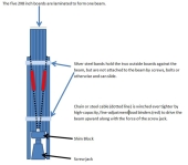
Short of a row of posts running down the middle of the quonset supporting the ridge, I think the only practical reinforcement would be cables, and there would need to be a cable at each rib pair so as to keep the stresses evenly distributed. I think the cables, if they went straight across, would want to be around the level of the top of the rollup door in the end wall. Unfortunately, that would be rather in the way of a lot of normal uses of the space. You might be able to make cable trusses with struts reaching down from the ridge, looking a lot like a series of drawn bows with arrows, with the cable attachments near the level of the bottom of the upper windows or top of the lower windows.

The cable ends would have to reach around each rib to bear on the outer surface beneath the roof sheathing, so as not to weaken the ribs by drilling holes or putting delamination stresses on them.

Anything like this would need calculations by a PE or other professional to size and locate elements and connections correctly.
 
John Weiland
pollinator
Posts: 2536
Location: RRV of da Nort, USA
719
  • Mark post as helpful
  • send pies
    Number of slices to send:
    Optional 'thank-you' note:
  • Quote
  • Report post to moderator
Urrggghh....thanks for the analysis, Glenn. I was afraid it was not going to be an easy fix. There used to be some barn straightening crews around locally at one time,......I may have to consult them to see if this is a job they may be able to handle. Thanks for the comments.
 
Glenn Herbert
Rocket Scientist
Posts: 4526
Location: Upstate NY, zone 5
574
5
  • Mark post as helpful
  • send pies
    Number of slices to send:
    Optional 'thank-you' note:
  • Quote
  • Report post to moderator
One other possibility may be to add diagonal posts as braces from the bottoms of the ribs to a point around halfway up. This would cut into the edges of the space some, but not obstruct the top/center at all, and probably be less tricky to do. You would need to first bring the profile into line so you could attach the posts.
 
Posts: 67
Location: high desert and mountains of Idaho and coastal Atlantic Canada (migratory)
8
  • Mark post as helpful
  • send pies
    Number of slices to send:
    Optional 'thank-you' note:
  • Quote
  • Report post to moderator

John Weiland wrote:Finally getting around to posting photos of Exhibit A. The problem project here is a 40 X 80 quonset that is sagging in the middle. The internal photo is of a separating wall that was installed to keep the front half of the building insulated and warmer than the back half. A large canvas tarp once hung down to serve as the divider. The beam that looks split is actually a few overlapping 2X6s....I can't imagine they were really placed there for structural integrity of the roof, probably just serving as a header for the door frame.
Would love to have the middle rib of the building jacked up past straight, so that the roof would bow upwards a bit in the middle instead of downward. The only thing I could envision was some high strength cabling spanning from one side to the other and anchored into a few of the ribs somehow, but worry about the stress on those timbers.
Any thoughts? Thanks.


Assuming that the ribs aren't rotted and kicking out at the bottom - is the wall straight at ground level?

Every rib needs the cable. Use fencing wire like This: 170 ft for $25 or $12.50 per rib. If you're feeling paranoid and think you need a PE then double it, or 4 strands per rib.

Use a come-a-long to pull two stands around each rib and secure somehow to keep the cables from wanting to slide up the rib. put a short piece of 1/2 conduit between the two wires every 6-8 ft and twist with a bar in alternating directions. pull it in a little at a time by tightening all the cables. Put a strong come-a-long alongside each cable as you twist it. The come-along does the pulling and the cable just holds it when you remove the come-along to the next rib. Jacking the ridge while tightening helps relieve the stress on the cables. It will move very slowly. If the distance to pull in is more than 3 inches per twist point 40 divide by 6ft would be about 6 points or 18 inches total pull. Measure this off the un-saged end wall If it is longer than that then you'll need to incorporate a turnbuckle like piece made from all-thread.

I have done a couple old barns with this swayback syndrome. none 40 x 80. 30 x 60 I have done and pulled it in about 8 inches.

warning: for some reason birds just love those wires much more than any boards or timber members. One of my customers didn't like aspect but didn't bitch much because we saved him tens of thousands of dollars. He hung canvas on the wires to thrart the birds. All across the nation old barns are slowly falling to the ground and everyone of them could be saved with some wire ... the magic tensile material the ancients never had.

.

 
Tom Turner
Posts: 67
Location: high desert and mountains of Idaho and coastal Atlantic Canada (migratory)
8
  • Likes 1
  • Mark post as helpful
  • send pies
    Number of slices to send:
    Optional 'thank-you' note:
  • Quote
  • Report post to moderator

Glenn Herbert wrote:Short of a row of posts running down the middle of the quonset supporting the ridge, I think the only practical reinforcement would be cables, and there would need to be a cable at each rib pair so as to keep the stresses evenly distributed. I think the cables, if they went straight across, would want to be around the level of the top of the rollup door in the end wall. Unfortunately, that would be rather in the way of a lot of normal uses of the space. You might be able to make cable trusses with struts reaching down from the ridge, looking a lot like a series of drawn bows with arrows, with the cable attachments near the level of the bottom of the upper windows or top of the lower windows.

The cable ends would have to reach around each rib to bear on the outer surface beneath the roof sheathing, so as not to weaken the ribs by drilling holes or putting delamination stresses on them.

Anything like this would need calculations by a PE or other professional to size and locate elements and connections correctly.


You know why this vault failed? It is the wrong shape. It is a Roman arch of true radius. It wasn't tall enough at the center. Roman arches stood because they were very thick, thich enough to be constructed as a radius yet still contain with-in them the "touching pieces of an arch." If it were a catenary the ribs of this vault ("Quonset") would have been under purely compressive force. Because they missed the correct catenary curve those ribs were under tensile forces and acted like a traditional truss. The catenary allows a building material, say like wheat straw, to be entirely under purely compressive forces.

In the late 17th century, the discovery for creating the strongest form of arch was realized. Robert Hooke had stated he found “the true mathematical and mechanical form of all manner of arches for building.” Initially encoded by means similar to that of an anagram (abcccddeeeeefggiiiiiiii-ilmmmmnnnnnooprrsssttttttuuuuuuuux), Hooke’s studies would later be revealed and applied. His string of letters, when re-arranged, held the details; “As hangs a flexible cable, so inverted, stand the touching pieces of an arch” (Ut pendet continuum flexile, sic stabit contiguum rigidum inversum).


.
 
John Weiland
pollinator
Posts: 2536
Location: RRV of da Nort, USA
719
  • Mark post as helpful
  • send pies
    Number of slices to send:
    Optional 'thank-you' note:
  • Quote
  • Report post to moderator
Thanks for these additional and encouraging comments, Tom. I have a few questions with regard to your described cable-based solution for re-straightening our quonset roof, but want to summarize the possible scenarios and add some additional information first.

One scenario here is to do nothing. If we do that, the roof will likely sag further, increasing the problem of the roof leaking which is what brought me to inquire about a solution in the first place. I bring up the leak because, even though I'm not seeing any obvious rot on account of water under the roof panels, that is not to say that rot does not exist. Nevertheless, all beams seem in reasonably good shape and none of the beams/ribs has disconnected from the wood base-plate, itself anchored to a cement skirt that defines the quonset foundation.

So a second scenario is to place a pole on the ground, which would necessarily need a footer of some type so as not to sink into the ground on account of the roof pressure, and have that pole holding up the roof after the roof has been jacked up and relieved back down onto the pole. This leaves a pole in the middle of the building which is acceptable to us and, assuming it would do the job, may be the least expensive and time-involved fix of all.

A third scenario is to use cross-beams originating from the base-plate near a rib and extending past the center-roof to a point opposite from that origin and affixed in some way to the rib after jacking of the roof. Upon settling of the roof back down, the cross beams would support the extra load. A third scenario similar to this which I was pondering was similar to the cross-beam approach, but instead has the beam originating from the base-plate and terminating at the central roof strut. The idea here would be to have a 'mirror', direct opposite, beam from the other side of the quonset meeting at the same point, but on the other side, of the central roof strut. Upon relieving support from the roof jacking, downward pressure from the roof would (might?) cause the new beams to "pinch" the central roof strut as they would both be inclined to move inward on account of the downward pressure. If this, or Glenn's option, were viable, I'm wondering how many beams would be needed to achieve our goal.

Finally, there is the cable option and I've added a few more photos for the discussion. First, the ribs are actually 3 laminated pieces of what looks like 1 X 6" or 1 X 8" lumber resulting in each rib being ~ 7" deep. This will pertain to what manner of attaching cables or support beams should be used that will not destroy the integrity of the rib. It would be easy enough to drill a hole through the beam adjacent to the wall so that cabling could run through the hole for attachment, but is this a sound idea?

Some additional information to add to the situation. As noted in another thread, we are located in a flood plain, the lines of which have been re-drawn due to the increased flooding over the past 20 years. The buildings, including the quonset, are essentially in a "no-build zone" due to these changes. It is quite likely that , if not moved to a new location, the building(s) will be demolished when we are done living here, probably in ~30 years or less. Outside of a few animals housed in the building, it sees no other traffic except my wife and I....visitors of any kind are few and far between. I add this to make it clear that we do not need to provide a fix for the next user, even though one obviously can't predict the future.

The cabling sounds like an interesting solution, but pretty extensive: I would certainly be using it if I were restoring an old barn that I would like to see survive as long as possible. I'm just not sure if this is what we want to do here, but worth exploring all the same. ......Could you please clarify how the come-along is used in the procedure you described? Do you have any photos of this procedure or can they be found on the internet? What pound-rating of come-along would be necessary for such a job? As it appears to be just the quonset's back-half of the roof that is sagging, would all of the ribs need cabling in that back half or only those under the dip in the roof? What placement on the rib would be optimal for optimum support once the jacks are relieved supporting the roof? What is the jack configuration for such a project?....a hydralic jack with a large pole or something industrial that is attached to a drive-in rig and is specialized for such a purpose?

I realize that this is akin to '20 questions', but could save us a lot of time and energy in the long run as I'm sure you are aware. Even in the short term, would hate to see increased water exposure from the leaking roof that may erode the roof integrity faster than it needs to. Again, much thanks for the comments and expert suggestions.
Composite.JPG
[Thumbnail for Composite.JPG]
 
Glenn Herbert
Rocket Scientist
Posts: 4526
Location: Upstate NY, zone 5
574
5
  • Mark post as helpful
  • send pies
    Number of slices to send:
    Optional 'thank-you' note:
  • Quote
  • Report post to moderator
I agree the arch shape is the cause of the stresses that are deforming it. From the interior picture, it wasn't quite a semicircular "Roman" arch, more a very modest Gothic pointed arch, but not nearly pointed enough to approximate a true catenary arch.

I see that one end is decidedly more sagging than the other; is the less deformed end where the dividing wall is? That would indicate that it might not take all that much structure to stabilize the roof.

With the goal defined as "stable for our lifetime" rather than "stable forever", and the stipulation that a few center posts may be acceptable, I think some form of that would be the way to go. I would use roundwood posts harvested from your land if you have enough, peeled and cut to appropriate lengths. Given the smallish nature of individual existing members, I think hardwood trees of maybe 6-8" dbh depending on actual center height would do the job, at something between 6' and 12' spacing. The simplest method would be to reinforce the ridgepole so it can distribute loads better to adjacent rib pairs, then cut the posts to correct length matching the end height, fix them into place at the tops, and have the bases resting on a continuous plank so they can start at an angle and have their bases sledgehammered bit by bit to end up beneath their tops. You might need double the final number of posts to be able to reduce the compressive friction on each post to where it is practical to hammer them. Maybe plan it so each post point is a double, with the starting configuration an inverted "V", ending as a tight pair of posts. I think it is likely that you might need to still plan on something like post pairs every 5', removing alternate sets after the final jacking is accomplished. The posts will *hold* a lot more than you are likely to be able to *raise*. Any surplus posts would become firewood. You would cut out the plank sections between posts after raising, so there would be just plank baseplates for each post.

The "cross-beams" approach would be more complex than necessary, and not better than the angled posts going from wall base to center ridge next proposed. Those angled posts would work excellently without impinging significantly on floor space. Their only drawback compared to the vertical center posts would be that a jack or several would be required to raise the roof before installing the posts; they could not be used by themselves as wedges to raise the roof, unless all partitions were removed from the barn.
 
Tom Turner
Posts: 67
Location: high desert and mountains of Idaho and coastal Atlantic Canada (migratory)
8
  • Mark post as helpful
  • send pies
    Number of slices to send:
    Optional 'thank-you' note:
  • Quote
  • Report post to moderator
The reason metal roofs pop their screws is because of the difference in thermal expansion between the steel vs. the wooden underlying structure. As the sheets expand and contract during daily, and seasonal temperature changes they alternately push and pull on the screw, kind of like a horse pushing on a fence post. The screw rotates under this movement.

It is the same effect as in both vinyl and aluminum siding. In both of those products the manufacturer uses slotted nail-holes and in application the nails are not to be driven home which allow the siding to expand and contract.

Plastic has a very high thermal expansion. Aluminum has less but twice as much as steel. To get a perspective assume wood is zero, steel is 1, aluminum is 2 and vinyl is 4. Steel is minimal compared to plastic and in most applications where the sheets of steel are short there is enough flex in the structure to not cause any problems. The longer the sheets of steel, the more the expansion differences accumulate and it then becomes a problem. I find it unbelievable that steel suppliers would sell 30-40 foot long sheets of roofing without warning the customer of this problem.

There are some manufacturers who have attachment systems that allow sliding movement, but they are super expensive. The simple solution is to install expansion joints - two or more small over-lapping sheets versus one long one.

Using old-school nails through the high ridge allowed some flex to occur. Screws in the valley only exacerbate the problem because it reduces the ability of the screw or the sheet to flex. Adding twice as many screws as recommended exacerbates the problem even further by reducing even further the ability of the sheet to flex. Heavy gage sheets vs. light gage sheets also make the problem worse.

.
 
Tom Turner
Posts: 67
Location: high desert and mountains of Idaho and coastal Atlantic Canada (migratory)
8
  • Mark post as helpful
  • send pies
    Number of slices to send:
    Optional 'thank-you' note:
  • Quote
  • Report post to moderator
The best way to understand this is to envision a truss. There are the two roof pieces that form the chevron-shaped roof, and the horizontal piece which forms the ceiling. The top two are under compression. As they are loaded by the roof the push against each other at the ridge and direct the force at the top of the walls. Without the horizontal piece the walls would bow out. The top two are under compression and the horizontal is under tension. The horizontal piece can be replaced with cable or chain, and sometimes is to give an open cathedral ceiling.

The Professional Engineers who designed the vault assumed that their arch shape would allow dispensing with the horizontal tensile element. They were wrong. The building still needs a horizontal tensile element. The end walls are not saging because the wall is the horizontal tensile element.

Consider the sag of the ribs to equate to the walls bowing, or leaning out. Jacking the ridge beam will not pull the walls back in plumb. It will only separate the ridge joint. You have to pull the walls in somehow and then retrofit the horizontal tensile element that the designers wrongly eliminated. Cables do both things, kills two birds with one inexpensive stone. You're just going to get an arm workout and your hands will be sore by the time you pull that old man of a barn back upright.

.
 
Glenn Herbert
Rocket Scientist
Posts: 4526
Location: Upstate NY, zone 5
574
5
  • Mark post as helpful
  • send pies
    Number of slices to send:
    Optional 'thank-you' note:
  • Quote
  • Report post to moderator
It's true that if the ribs have taken a set in the bowed position, they will resist straightening, and tend to pull apart at the ridge if the ridge is jacked up. If they have not set, or if they will regain their original shape with a slow jacking (over a period of weeks maybe), then they will no longer need a cable element to keep them from bowing, as the force causing the bowing will have been eliminated.

The roof at the end walls is not sagging because the walls are giving vertical support to the ridge, and there is no horizontal force that needs to be resisted.

To counteract the separating tendency, I would suggest tying the rib pairs together with tension boards just below the ridge. This is not a perfect solution, but should be good enough. The ideal tie location would be at the top of the ridge, which might be doable by drilling through the ridge and attaching lengths of threaded rod or bolts with steel brackets bolted to the sides of the ribs near the top.

If you did use some cables, they would work together with the jacking posts to reduce the stress on each element. You might want to start with the easiest method, and plan to add some of the other types of movement inducers if the effort becomes too difficult.
 
John Weiland
pollinator
Posts: 2536
Location: RRV of da Nort, USA
719
  • Mark post as helpful
  • send pies
    Number of slices to send:
    Optional 'thank-you' note:
  • Quote
  • Report post to moderator
@Glenn H.: "....is the less deformed end where the dividing wall is? That would indicate that it might not take all that much structure to stabilize the roof. "

The dividing wall is right smack in the middle of the structure. So the sagging point is right about dead center of the north half of the building.
Based on your comments and those of Tom T., I'm considering a hybrid fix....using cableing and come-alongs to provide tension, possibly a jack against the center rib to provide lift, and then using a cut telephone pole to provide final support.....we don't have the right trees in the area of the height needed to be able to cull one from our land for that purpose. In the end, the cables can be tightened to assist in the support as well.

So two last questions that I'm curious about: (1) Could C-clamps provide sufficient 'hold' to keep the ridge from splitting apart during jacking if the sidewalls have in fact become rigidified in their current (sagged) form? And (2) given the photo of one of the ribs above, how best to fix a cable around that rib without having to go through the roof to provide sufficient anchor to the cable with minimal risk of breaking through the rib?

It's funny, now when I'm driving the countryside, I'm noticing all the quonsets,.....and which ones have right mount of "point" versus "curve". Again, thanks for great ideas and comments.
 
Glenn Herbert
Rocket Scientist
Posts: 4526
Location: Upstate NY, zone 5
574
5
  • Mark post as helpful
  • send pies
    Number of slices to send:
    Optional 'thank-you' note:
  • Quote
  • Report post to moderator
The separation issue would not be the ridge itself splitting, it would be the ribs separating from the ridge at the joints. You could theoretically fasten the ribs more securely to the ridge, but the best fix would be to fasten them to each other, eliminating the tendency of fasteners to pull out of ridge attachments. The stress would be parallel to the rib side surfaces, so stout through bolts would work without depending on threads into wood.

If there is no space between the ribs and the roof sheathing, I would drill through the ribs an inch or two from the outer surface and put pins or bolts through, with attachment to the cable on each side so as not to twist the ribs. This would definitely weaken the rib, so the cables would need to be permanent, taking the bending stress off the ribs at the point of attachment. If you can slide a steel plate between the rib and sheathing, and then bend the plate so it can be bolted to cable attachments, that may work best of all... depends on how much force you are going to put on each cable.

If you are only planning on one post to support the middle of a 40' length of sagging roof, I would strongly urge beefing up the ridge first. A 10' or so timber, or a couple of timbers, one 12' and one beneath it 6',should spread the load reasonably well. (Think "leaf spring".) You would need to brace these so they don't buckle sideways, of course.
 
John Weiland
pollinator
Posts: 2536
Location: RRV of da Nort, USA
719
  • Mark post as helpful
  • send pies
    Number of slices to send:
    Optional 'thank-you' note:
  • Quote
  • Report post to moderator
Wow.....2 years since the last entry.  Today saw a tragic end to the story,......though fortunately we've found no fatalities yet (pretty much all accounted for at this point).  We dithered too long looking for a fix.  And today Mother Nature's patience wore out......she dealt the final blow.  Too much snow built up on the roof......with the predicted consequences.  The silver lining:  Time to start planning for a new, smaller, more robust building.
Quonset1.jpg
[Thumbnail for Quonset1.jpg]
Quonset2.jpg
[Thumbnail for Quonset2.jpg]
Quonset3.jpg
[Thumbnail for Quonset3.jpg]
Quonset4.jpg
[Thumbnail for Quonset4.jpg]
 
steward
Posts: 15505
Location: Northern WI (zone 4)
4846
7
hunting trees books food preservation solar woodworking
  • Mark post as helpful
  • send pies
    Number of slices to send:
    Optional 'thank-you' note:
  • Quote
  • Report post to moderator
Wow John, I'm sorry to hear she fell down.  When I saw this thread pop up I thought either someone was wondering how it did or it was an obituary...
 
John Weiland
pollinator
Posts: 2536
Location: RRV of da Nort, USA
719
  • Likes 1
  • Mark post as helpful
  • send pies
    Number of slices to send:
    Optional 'thank-you' note:
  • Quote
  • Report post to moderator
Thanks, Mike.  A pretty big disaster all the way around.....just more frustrating given the winter we've had.  And the accumulation that caused the collapse is only adding to flood worries.  Hoping for the mildest of spring seasons at this point....
 
John Weiland
pollinator
Posts: 2536
Location: RRV of da Nort, USA
719
  • Mark post as helpful
  • send pies
    Number of slices to send:
    Optional 'thank-you' note:
  • Quote
  • Report post to moderator
....and a bit of the Phoenix rising from the ashes.  A few pics to commemorate a long and rather arduous summer, with more chores to go this fall.  The photos above say it all in terms of where we started from on March 9th, the day the quonset collapsed from snow load.  in the next few photos are the removal of the quonset, a new site prep, a new building, an addition to the building for hay, a new chicken building,.....and more hopefully to follow.   Just amazing that a crew of 2 guys and a Bobcat erected the new 30 X 40 building in 3 days!  The chicken house roof is cut pieces from the quonset....we salvaged as much of the metal that we could and it's still being used for other projects.
Destroyed.jpg
[Thumbnail for Destroyed.jpg]
JohnnyCat.JPG
[Thumbnail for JohnnyCat.JPG]
P1180765.JPG
[Thumbnail for P1180765.JPG]
P1180812.JPG
[Thumbnail for P1180812.JPG]
Day1a.jpg
[Thumbnail for Day1a.jpg]
Day2a.jpg
[Thumbnail for Day2a.jpg]
Day3a.jpg
[Thumbnail for Day3a.jpg]
FramingChickHouse.jpeg
[Thumbnail for FramingChickHouse.jpeg]
FramingChickHouse2.jpeg
[Thumbnail for FramingChickHouse2.jpeg]
WithRoof-Gable.JPG
[Thumbnail for WithRoof-Gable.JPG]
ChickHausAlso.jpeg
[Thumbnail for ChickHausAlso.jpeg]
 
John Weiland
pollinator
Posts: 2536
Location: RRV of da Nort, USA
719
  • Mark post as helpful
  • send pies
    Number of slices to send:
    Optional 'thank-you' note:
  • Quote
  • Report post to moderator
Oooops....forgot the addition to the main building for hay:
HayBarn.jpg
[Thumbnail for HayBarn.jpg]
BarnDone.jpg
[Thumbnail for BarnDone.jpg]
HayBarnInside.jpg
[Thumbnail for HayBarnInside.jpg]
 
Posts: 9002
Location: Victoria British Columbia-Canada
707
  • Mark post as helpful
  • send pies
    Number of slices to send:
    Optional 'thank-you' note:
  • Quote
  • Report post to moderator
Did it come down hard enough to ruin everything inside, or were you able to salvage much of it?
 
John Weiland
pollinator
Posts: 2536
Location: RRV of da Nort, USA
719
  • Likes 1
  • Mark post as helpful
  • send pies
    Number of slices to send:
    Optional 'thank-you' note:
  • Quote
  • Report post to moderator

Dale Hodgins wrote:Did it come down hard enough to ruin everything inside, or were you able to salvage much of it?


Hi Dale,

We did lose a lot of wood that we would have preferred keeping.  The way the walls collapsed, it was fortunate that no one nor animal was hurt.  Nevertheless, with the weeks that followed the collapse, it became quite precarious to walk around within the building.  On windy days, sheets of metal would be swinging back and forth and pretty bad creaking could be heard as the building wanted to settle.  So we decided to save as much plywood as possible, one large feed bin, a few windows, and some random tools.  The rest disappeared in a single day of demolition with about 10 truckloads assisting the demolition crew.  You can see the old quonset perimeter at the edge of the new chicken house.  Also.....the cruddy-looking lean-to at the back of the new chicken house was attached to the quonset.  That large Cat backhoe operator managed to remove the quonset without touching several smaller attached buildings that we are still using.....the one noted was placed onto skids and pulled with my tractor back to where it could be merged with the chicken hut.  So some salvaged plywood, metal, and a few windows are resurrected in several of the new buildings going up.  Although the major new building was new construction, I built the attached hay barn and the chicken building using the old quonset metal as roofing and occasionally a beam or two was some large piece pulled from the wreckage. Not shown are some twin-wall plexiglass greenhouse panels salvaged from a local hailstorm....they are cut to size to fit in the south-facing rough-in holes in the chicken house and will provide much relief from the winter chill. Glad most of it is now done to satisfaction before the snow flies!
 
Posts: 1
  • Likes 2
  • Mark post as helpful
  • send pies
    Number of slices to send:
    Optional 'thank-you' note:
  • Quote
  • Report post to moderator
I completely recognize that this is a five year old comment, but I've been scouring what feels like the ENTIRE internet and I keep coming back to this thread. I'm working on a similar problem right now with a client's gothic arch, which has a slight sag in the middle, and the cause of this is, apparently, completely open to all kinds of theoretical ideas created by the people I'm dealing with, mostly a stubborn architecture school dropout and his army of formulas and terms that I feel like, are really mudding up my ability to look at the problems and develop a plan for a solution based on what's THERE, what's NOT, and how to determine the least intrusive way of supporting this (so far, fairly light) sagging at the center ridge.
I'm wondering if, well of course if anyone reads this, if I could throw out the details of the roof situation I have in front of me, and hopefully you all, with what I can tell is knowledge of and oodles of experience with these types of structures that I have AT HAND, may be able to help me better understand what's happening with this barn? Because I do feel like I have a pretty good grasp on it, but after two exhausting hours on the phone with Mr. architecture, I can't even put what I know into a cohesive sentence any longer. This truss analogy keeps popping back in my head....

Thanks to anyone who reads or replies, sorry if I wrote this in the wrong area, I've never really participated in a forum and I'm sure I'm doing it all wrong.
 
master pollinator
Posts: 4953
Location: Due to winter mortality, I stubbornly state, zone 7a Tennessee
2118
6
forest garden foraging books food preservation cooking fiber arts bee medical herbs
  • Mark post as helpful
  • send pies
    Number of slices to send:
    Optional 'thank-you' note:
  • Quote
  • Report post to moderator
I don't have the expertise to help. However, I can tell you that pictures will be beneficial to help identify solutions.
 
Mike Haasl
steward
Posts: 15505
Location: Northern WI (zone 4)
4846
7
hunting trees books food preservation solar woodworking
  • Mark post as helpful
  • send pies
    Number of slices to send:
    Optional 'thank-you' note:
  • Quote
  • Report post to moderator
You bet, post some pics and someone will likely give you advice.  This thread isn't old, it's at the top of the page
 
I'm not sure if I approve of this interruption. But this tiny ad checks out:
rocket mass heater risers: materials and design eBook
https://permies.com/w/risers-ebook
reply
    Bookmark Topic Watch Topic
  • New Topic