• Post Reply Bookmark Topic Watch Topic
  • New Topic
permaculture forums growies critters building homesteading energy monies kitchen purity ungarbage community wilderness fiber arts art permaculture artisans regional education skip experiences global resources cider press projects digital market permies.com pie forums private forums all forums
this forum made possible by our volunteer staff, including ...
master stewards:
  • Nancy Reading
  • Carla Burke
  • r ranson
  • John F Dean
  • paul wheaton
  • Pearl Sutton
stewards:
  • Jay Angler
  • Liv Smith
  • Leigh Tate
master gardeners:
  • Christopher Weeks
  • Timothy Norton
gardeners:
  • thomas rubino
  • Jeremy VanGelder
  • Maieshe Ljin

Solar panels not charging batteries

 
Posts: 4
  • Mark post as helpful
  • send pies
    Number of slices to send:
    Optional 'thank-you' note:
  • Quote
  • Report post to moderator
Please help or assist in my charging issues.

Firstly I am running 5, 200W 24V panels which are wired in parrael with all panels fused. Solar regulator is PWM 50 amp unit. Battery bank, I am running x4, 12v 200 amp batteries wired to produce 24v. Inverter / charger unit, rated at 3000 watt. Cable from panels to battery bank is three fase Orange power cable which I believe is rated at 10mm which given there are 5, cables I have two cables linked up for positive and same for negative so should have overall rating of 20mm. Length of cables from panels to regulatior is around 30 metres.

Voltage test just after panel was 42 v and same voltage tested just before regulatior 30 meters away from panels.

Charging issue, batteries will charge through inverter/ charger powered via generator but not through solar, regulator has been changed over but with replacement unit still doing the same and not charging.

Regulator specs, 12 /24v , 50amp Low voltage connection 25.2v which batteries have been as low as 24v

Question, if each solar panel is rated at 10amp x 5 = 50amp , being the regulator is only rated at 50amp would or could this be slightly undersized ?

Any help would be much appreciated as my Melbourne supplier is being of no help
 
pollinator
Posts: 684
Location: Richmond, Utah
33
  • Mark post as helpful
  • send pies
    Number of slices to send:
    Optional 'thank-you' note:
  • Quote
  • Report post to moderator
Hi Darren,

The first thing that I would check would be charge controller output. Ensure that it is set for 24v and that no fuses anywhere are blown. The charge controller may be a bit undersized, but that should only limit performance. Check over the batteries and ensure they are 12v and 2 are in parallel and 2 in series. Most charge controllers have at least an led diagnostic, what does this show? What is the max voltage rating for your charge controller? If the panel voltage exceeds the controller rated input, you might have fried the controller.
Good luck, I know this stuff can be really frustrating.
 
Darren Carson
Posts: 4
  • Mark post as helpful
  • send pies
    Number of slices to send:
    Optional 'thank-you' note:
  • Quote
  • Report post to moderator
Hi Bill
Thanks for replying
This regulator is the second one received from my supplier as I thought the first one was faulty.
The LCD type display shows system working correctly with battery voltage and bar type graph on how much % batteries have in them.
It also should have a arrow indicator when power is going into battery bank which has never come on.
Next test I was thinking was to put multi meter on battery bank with solar connected to see if any readings.
 
Bill Bradbury
pollinator
Posts: 684
Location: Richmond, Utah
33
  • Mark post as helpful
  • send pies
    Number of slices to send:
    Optional 'thank-you' note:
  • Quote
  • Report post to moderator

Bill Bradbury wrote:Hi Darren,

What is the max voltage rating for your charge controller? If the panel voltage exceeds the controller rated input, you might have fried the controller.


It sounds like a high panel voltage to me for a parallel wired system. Typically, I don't see over 37v from a single panel even in the most direct sunlight. Do you have them in series parallel? Then panel voltage could get to 74v at times, exceeding the rating of older PWM controllers that were rated at 60v.

 
Darren Carson
Posts: 4
  • Mark post as helpful
  • send pies
    Number of slices to send:
    Optional 'thank-you' note:
  • Quote
  • Report post to moderator
Solar panels are 200W x 24V wired in parallel
Regulator is rated to 50V
Battery bank, running 4x 200amp 12V wired in series and parallel producing 24V.
 
Bill Bradbury
pollinator
Posts: 684
Location: Richmond, Utah
33
  • Mark post as helpful
  • send pies
    Number of slices to send:
    Optional 'thank-you' note:
  • Quote
  • Report post to moderator
I'm sorry that I can't be more helpful, I'm not an expert as solar electric is more of a hobby than a job for me.

If I were you, I would check the wiring and fuses one more time and if that didn't work; try to return the charge controller and get a mppt controller rated for 200v.
 
Darren Carson
Posts: 4
  • Mark post as helpful
  • send pies
    Number of slices to send:
    Optional 'thank-you' note:
  • Quote
  • Report post to moderator
Thanks Bill
Changing the controller to a different type might be a option but new to be certain that this is the main issue.
Also keeping in mind all equipment set up is new.
 
Posts: 217
Location: Ontario
13
  • Mark post as helpful
  • send pies
    Number of slices to send:
    Optional 'thank-you' note:
  • Quote
  • Report post to moderator
The issue is simple you have two batteries in series and two in parralel using the same 24v charger therefore there is not enough current to charge the batteries. Think of it this way, you add a battery to your car without adding another alternator and your batteries don't charge fully because you have doubled the load without upgrading the supply.

Even though it is a 40 amp charger it is not producing 40amps to the battery and your current is being devided between two battery banks. Divide your banks into two banks of of 24v then add separate chargers to each bank. Join the two banks in parralel. Two panels per bank would be enough to charge each bank. You could add three panels in parralel per bank with a 40 amp charger per bank for extra charging power in lower sunlight levels.
 
Posts: 10
  • Mark post as helpful
  • send pies
    Number of slices to send:
    Optional 'thank-you' note:
  • Quote
  • Report post to moderator
Steve from everything I have read what you have said just doesn't make sense to me. Doesn't the charge rate of any lead acid battery bank need/should be 10-13% of the total amperage of the bank. His battery bank total is 400 so charging amperage should be between 40 and 53 amps. So to me it sounds like he is right in the ball park of the total bank charging needs. From what your saying it sounds like if he gets another charge controller it will up his charging amperage, isn't the amperage Dependant on the panels out put not so much the controller (minus inefficiencies with in the system) especially seeing it's a pwm control unit. I'm still learning all this stuff and sometimes I miss key information about how stuff works so please correct me if I'm wrong because I don't want to learn the hard way.
 
Steve Harvey
Posts: 217
Location: Ontario
13
  • Mark post as helpful
  • send pies
    Number of slices to send:
    Optional 'thank-you' note:
  • Quote
  • Report post to moderator

scott bendtson wrote:Steve from everything I have read what you have said just doesn't make sense to me. Doesn't the charge rate of any lead acid battery bank need/should be 10-13% of the total amperage of the bank. His battery bank total is 400 so charging amperage should be between 40 and 53 amps. So to me it sounds like he is right in the ball park of the total bank charging needs. From what your saying it sounds like if he gets another charge controller it will up his charging amperage, isn't the amperage Dependant solely on the panels out put (minus inefficiencies with in the system) especially seeing it's a pwm control unit. I'm still learning all this stuff and sometimes I miss key information about how stuff works so please correct me if I'm wrong because I don't want to learn the hard way.


Your question is actually the answer. If he needs 40 amps to charge the batteries, the 40 amp charger is not producing 40 amps, that 40 amp rating is a rating for the input going into the charger not out of it. the reason why is because, if you have multiple solar panels hooked up to the charger, and your current coming out of the panels fluctuates between lets say 0 and 30 amps on a really sunny day. Having a 40 amp charger means, The charger is safe to use with "input currents" from the panels up to 40 amps. It is usually good to over size the charger in terms of a 10 20 30 or 40 amp referring to the "input current" not the output.

all lead acid batteries usually charge in 3 stages which are, [1] constant-current charge, [2] topping charge and [3] float charge. Most lead acid chargers only produce a maximum of 15amps to the battery, sometimes less. Having both batteries draw current from the same charger at the same time will not work. sort of like why you don't put all the appliances in your house on the same circuit breaker. Certain devices or loads require dedicated circuits because they draw a lot of current.

The use of battery isolators allow two batteries to charge off one charger because it allows the batteries to charge one at a time by acting as an automatic switch. However they are known to destroy batteries as well, and should not be used in a battery bank when you can just buy more chargers and put all your batteries on dedicated chargers.
 
Steve Harvey
Posts: 217
Location: Ontario
13
  • Mark post as helpful
  • send pies
    Number of slices to send:
    Optional 'thank-you' note:
  • Quote
  • Report post to moderator
Scott take a look at this marine charger, it is designed to plug into a 120v 40 amp household power source, and supplies enough current to charge 4 deep cycle lead acid batteries. I posted this in your other thread. If you read the first sentence of the description it says, "The Dual Pro Sportsman Series charger will deliver up to 10 amps PER BANK." The "per bank" part is important. When you are charging batteries or powering a device that requires 1 amp of current, you must be able to provide 1 amp of current to do the job. Whether it is supplied by AC or DC and being converted, 1 amp supplied equals 1 amp consumed. So if a battery needs 10 amps to charge, and you are charging 2 batteries in series that demand 10 amps each, but you are only supplying 10 amps. Can you charge the batteries?

http://www.batterystuff.com/battery-chargers/12-volt/marine-chargers/DPSS4.html

The reason why this makes sense is because of one very reliable law of electricity called Ohms Law.

Ohm's Law deals with the relationship between voltage and current in an ideal conductor. This relationship states that: The potential difference (voltage) across an ideal conductor is proportional to the current through it. The constant of proportionality is called the "resistance", R.: I=V/R

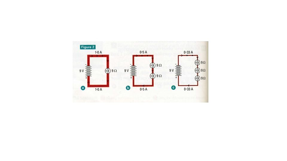
Notice when there is only one circuit for current to flow the supplied current is halved, and is now .5 amp with just 1 resistor, and then halved again when there are two, and halved again when there are 3.


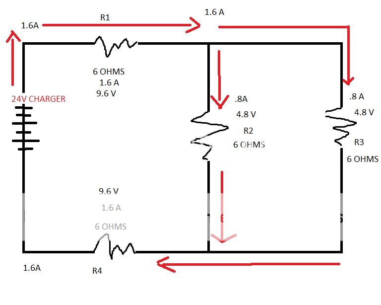
If you look at what the original poster said about his batteries, "I am running x4, 12v 200 amp batteries wired to produce 24v." you see that he is running 4 batteries off one charger, 2 in series and 2 in parallel. So if we apply ohms law to that knowing that the battery charger is supplying 10 amps to charge the batteries during the bulk phase of charging. Each battery is only getting 5 Amp in bulk charge. Because there are 2 resistors(24v batteries) hooked up in a series circuit. Then as the battery charges the current lowers going into the next charging phases. When the current gets to the second charging phase the Topping Charge. If the supplied current is 2 amps the batteries are actually seeing only 1 amp.

I would not be surprised that if you left the batteries charging through your panels for a month, they would probably charge nearly full.

 
Posts: 7
2
  • Mark post as helpful
  • send pies
    Number of slices to send:
    Optional 'thank-you' note:
  • Quote
  • Report post to moderator
Hi,

I just registered to help cleaning up the mess that start to unfold here. I agree with Scott, Steves reasoning doesn't make much sense to me either.
Steve, you're mixing serial and parallel connections, talking of one and drawing up the other. The battery bank has a voltage of 24 V and a capacity of 400 Ah. So it can be charged with Darren's setup, though it would take around two to three sunny days to fully charge it from empty.

Darren, your regulator is a bit undersized, but that cannot be the problem. It only means that you might loose some of the output of your panels, when they could provide more than they're rated for, witch can happen under certain conditions. Assuming the 24 V to be Vmpp, the 10 A must be the short circuit rating, so your current rating at mpp is below that value and you even got some reserve with the 50 A of your regulator.

Does the regulator display its input voltage? What are the input specs of the regulator? Are the 25.2 V an input spec? What is the 50 V rating exactly saying? The regulator has a minimum start up voltage and a maximum input voltage. If the minimum value is above the measured 42 V, that is the reason it doesn't start. If the maximum value is below the 42 V, it's probably grilled.
If you give me the names of the panels and the regulator and I can find specs online, I should be able to give you step by step guidance to find the problem.
 
Steve Harvey
Posts: 217
Location: Ontario
13
  • Mark post as helpful
  • send pies
    Number of slices to send:
    Optional 'thank-you' note:
  • Quote
  • Report post to moderator

Samuel Jaißle wrote:Hi,

I just registered to help cleaning up the mess that start to unfold here. I agree with Scott, Steves reasoning doesn't make much sense to me either.
Steve, you're mixing serial and parallel connections, talking of one and drawing up the other. The battery bank has a voltage of 24 V and a capacity of 400 Ah. So it can be charged with Darren's setup, though it would take around two to three sunny days to fully charge it from empty.

Darren, your regulator is a bit undersized, but that cannot be the problem. It only means that you might loose some of the output of your panels, when they could provide more than they're rated for, witch can happen under certain conditions. Assuming the 24 V to be Vmpp, the 10 A must be the short circuit rating, so your current rating at mpp is below that value and you even got some reserve with the 50 A of your regulator.

Does the regulator display its input voltage? What are the input specs of the regulator? Are the 25.2 V an input spec? What is the 50 V rating exactly saying? The regulator has a minimum start up voltage and a maximum input voltage. If the minimum value is above the measured 42 V, that is the reason it doesn't start. If the maximum value is below the 42 V, it's probably grilled.
If you give me the names of the panels and the regulator and I can find specs online, I should be able to give you step by step guidance to find the problem.


I don't think I am that off. If you look at the circuit you will see that current is split through the parallel batteries and charge time takes twice as long if not longer. If the standard charging time for 1 battery is a minimum of 12-15 hours. The two 24v batteries would take 24-30 hours to charge through solar. The amount of usable sunlight needed to produce 24 volts to charge the batteries would vary depending on where you live. Where I live the amount of sunlight available in any season other than mid summer would be around 30 to 40 hrs. in a week. So in a bad week in terms of sunlight, that 400ah battery bank would take a week or longer to charge, and would last me 4 hrs running 1000 watts of devices. Therefore you can not use this battery circuit with those batteries in a successful solar battery bank. It takes too long to charge the batteries and you can not power your devices for very long. If you scrapped the complex battery circuit and charged the 2 12 volt batteries in series with separate chargers your charging time will be cut in half.


This circuit is to show 4 batteries in a series parallel combination circuit, 2 in series 2 in parallel. The 6 ohm figure is made up and is just to show that all batteries have the same resistance.
 
Samuel Jaißle
Posts: 7
2
  • Mark post as helpful
  • send pies
    Number of slices to send:
    Optional 'thank-you' note:
  • Quote
  • Report post to moderator

Steve Harvey wrote:If you scrapped the complex battery circuit and charged the 2 12 volt batteries in series with separate chargers your charging time will be cut in half.


No it isn't. You have a certain amount of power [W] your panels put out. And with that amount of power you get a certain amount of energy in one hour [Wh]. The time it takes to charge your battery depends on the power output [W] and on the capacity [Wh] of your battery. Now in the setup referred to here, the charger usually is able to pass the full output of the panels on to the battery. Another charger doesn't add any power output to the panels. To cut charging time in half, you have to double the power you're charging with and to do that, you can't just split your battery and add another charger, you have to double your panels, too.

Besides, that is not on the topic, since the problem isn't that the batteries are charged to slow, but that the charger doesn't even charge the battery at all. It seems to pass nothing of the energy available on to the battery. And that can't have to do anything with to small charging currents.
 
scott bendtson
Posts: 10
  • Mark post as helpful
  • send pies
    Number of slices to send:
    Optional 'thank-you' note:
  • Quote
  • Report post to moderator
I see what you are saying Steve but the charge controller allows more than ten amps through especially if it's a mppt controler.
 
Steve Harvey
Posts: 217
Location: Ontario
13
  • Mark post as helpful
  • send pies
    Number of slices to send:
    Optional 'thank-you' note:
  • Quote
  • Report post to moderator

Samuel Jaißle wrote:

Steve Harvey wrote:If you scrapped the complex battery circuit and charged the 2 12 volt batteries in series with separate chargers your charging time will be cut in half.


Besides, that is not on the topic, since the problem isn't that the batteries are charged to slow, but that the charger doesn't even charge the battery at all. It seems to pass nothing of the energy available on to the battery. And that can't have to do anything with to small charging currents.


I think he said that the charger is charging through the generator and not the solar panels, so there is power going through . He said that he is using 5 panels wired in parallel meaning they are producing 24 volts. After researching mppt chargers as I am not too familiar with them. I noticed the specs of a 50 amp mppt charger required an input voltage of 30 to 150 volts dc meaning the charger is designed to work with higher input voltages. It is possible that the charger will not charge the batteries until it reaches the required input voltage to operate?
 
Steve Harvey
Posts: 217
Location: Ontario
13
  • Mark post as helpful
  • send pies
    Number of slices to send:
    Optional 'thank-you' note:
  • Quote
  • Report post to moderator
Samuel, would charging batteries in a series/parallel circuit, where lead acid batteries spent a few days to a week below being fully charged cause a build up of sulfate inside? Charging the batteries for less than 8 hours a day and letting them sit over night would cause the batteries to build up different internal resistances and cause the batteries to become electrically unequal. Wouldn't this be damaging to the batteries and greatly reduce their life span and performance?
 
Samuel Jaißle
Posts: 7
2
  • Mark post as helpful
  • send pies
    Number of slices to send:
    Optional 'thank-you' note:
  • Quote
  • Report post to moderator

Steve Harvey wrote:I think he said that the charger is charging through the generator and not the solar panels, so there is power going through


As I understand this

Darren Carson wrote:batteries will charge through inverter/ charger powered via generator but not through solar


the batteries a charged from AC side, but not from DC side. There are two different devices at work here, and the regulator on the solar (DC) side seems not to let any power through.

Steve Harvey wrote:It is possible that the charger will not charge the batteries until it reaches the required input voltage to operate?


Yes, that is one possible problem. That's exactly why I asked for more specs or the name of the panels and regulator.

Steve Harvey wrote:He said that he is using 5 panels wired in parallel meaning they are producing 24 volts.


You can't always assume that, only cause they’re rated for 24 V. This rating tells you the MPP voltage at standard radiation (1000 W/m²) and standard temp (23°C, if I remember right). Seems he had a open circuit voltage of 42 V. This is again why I asked for the name of the panels.

Steve Harvey wrote:would charging batteries in a series/parallel circuit, where lead acid batteries spent a few days to a week below being fully charged cause a build up of sulfate inside?


I'm not an expert on lead acid batteries, my knowledge is focused more on lithium batteries. But according to my researches about two years ago, the one point, that speeds up aging of acid batteries the most, is discharging to a low level. It is recommended to use only about 60% of the capacity of a lead acid battery. Witch means, you should not discharge them below 40%. This does more harm than charging them slowly. So it is better to have batteries with higher capacity and only using part of it, that have smaller batteries and using more of the capacity (discharging them to a lower level) and charging them at standard rate.

And then finally to correct the schematics, this is how the batteries really are connected:

 
Posts: 30
Location: Altadena, CA, USA
  • Mark post as helpful
  • send pies
    Number of slices to send:
    Optional 'thank-you' note:
  • Quote
  • Report post to moderator
Hi Darren,

Can you provide drawings of your wiring as well as make & model of the used equipment?
Going with the information you have provided:

-42V seems right for panels made from 72 individual cells
-"Low voltage connection 25.2v which batteries have been as low as 24v"
>>do you mean "low voltage disconnect"? 25.2 and even 24 is to high for that value. Go for 23 - 22V.
-Question, if each solar panel is rated at 10amp x 5 = 50amp , being the regulator is only rated at 50amp would or could this be slightly undersized ?
>>50A is the short circuit current, you will never get that in a real world environment. So 50A rating is OK.

How do you know that no charging is happening thru the panels?

Markus
 
Posts: 596
Location: South Tenerife, Canary Islands (Spain)
14
forest garden trees greening the desert
  • Mark post as helpful
  • send pies
    Number of slices to send:
    Optional 'thank-you' note:
  • Quote
  • Report post to moderator
You can charge 10+ batteries up if you want with the setup described, it doesn't matter how many amps go to the battery, that just means it will charge slower. What matters here is getting the voltage right. If you're supplying 42V to a 24V charge controller then this is your problem.

Solar panels rated 24V will have 72x 0.55V cells in series. Total V in an impossible no losses scenario is 39.6V. There is a schottsky diode in the panel to stop the battery discharging thru the panels during darkness, this will use up a ~1.5V per diode, so as previously stated the most you're ever going to see is 37V but more realistically you're going to see a bit less. The charge controller will block current from passing if it sees more than ~37V. A faulty panel can't increase this, only faulty setup. Somehow more than 72 cells have been put into series, probably by having one of the 5 panels in series instead of parallel or maybe 1 of the panels is a 48V model.

Remove each panel one at a time until the problem goes away. If you've still got the problem with just one panel then put it aside and rebuild the setup one panel at a time with the other 4 panels.
 
Posts: 1
  • Likes 1
  • Mark post as helpful
  • send pies
    Number of slices to send:
    Optional 'thank-you' note:
  • Quote
  • Report post to moderator
Hi,
I have had similar problems on a boat.
2x 80w panels 12v were giving 8amps in sunny France.
Then for no apparent reason they stopped charging.
Tried 2 different charge controllers and still no charge.
This was 18 months ago.
Our batteries were getting old almost 8 years. 4 x 160ah agm.
New batteries fitted and suddenly the batteries are being charged by the solar panels.
No other changes to wiring etc. made.
So if you have old batteries (ours after charging via battery charger were showing 12.6v) and your solar panels are not working, think about new batteries.
It worked for us.


Posts: 11
  • Mark post as helpful
  • send pies
    Number of slices to send:
    Optional 'thank-you' note:
  • Quote
  • Report post to moderator

Darren Carson wrote:

Voltage test just after panel was 42 v and same voltage tested just before regulatior 30 meters away from panels.

Charging issue, batteries will charge through inverter/ charger powered via generator but not through solar, regulator has been changed over but with replacement unit still doing the same and not charging.

Regulator specs, 12 /24v , 50amp Low voltage connection 25.2v which batteries have been as low as 24v

Question, if each solar panel is rated at 10amp x 5 = 50amp , being the regulator is only rated at 50amp would or could this be slightly undersized ?

Any help would be much appreciated as my Melbourne supplier is being of no help


Your regulator maybe ok its rated at 50amps however, your panels if new maybe output more power than that stated on the power plate. Most quality panels allow for initial light induced degradation and throw in some free power to compensate. Once a panel is exposed to light this free power soon drops off and power is then either as rated or considerably lower however, remains within warranty. Certain panels have no light induced degradation, although another topic. Since you live within a high irradiance area its possible those panels kick out maximum power (even above rated power), if your charge controller were poorly constructed then its going to be severely tested maybe to point of destruction if running at rated power or beyond. Need to somehow obtain what practical rather than theoretical amperes are really flowing throw the unit.

Wrote that the batteries charge when a charger is presented this powered from a generator thus are bypassing the solar panels and charge controller via disconnection or a double pole switch. Ever thought of just hooking up that DC output to your PWM? After all how does it know whether the DC current comes from a panel or a 24 volt charger or any other 24 Volt DC source of adequate ampere draw. Its one way to obtain what is going on.

Start that process of elimination.

While that is thought about ask the question of what task your PMW, is suppose to achieve.

Any photos?


Sounds fishy. It smells fishy too. You say it's a tiny ad, but ...
12 DVDs bundle
https://permies.com/wiki/269050/DVDs-bundle
reply
    Bookmark Topic Watch Topic
  • New Topic