|

|
|
|
|

|

|

|

|

|
 4
4


thomas rubino wrote:Very Cool Peter!
Besides being functional it is a work of art!
Congrats on version #5!
Is there a version #6 floating about your head?
Self-Proclaimed Renaissance Man and Gizmologist.
Shodo
Mountains and Waters Alliance
Cristobal Cristo wrote:Shodo,
In theory you could build 100mm/4" BBR system. The ISA for such a heater would be around 2.4 m2, so the heater could be 30x30x55". However the small systems, with riser diameter less than 5" may not always work as desired. They are more demanding in workmanship and material selection.
Shodo
Mountains and Waters Alliance
7
Self-Proclaimed Renaissance Man and Gizmologist.
1
Shodo
Mountains and Waters Alliance
8


.jpg "Filename: IMG_0345-(1).jpg
Description: heat damage on riser and tube weld")
Self-Proclaimed Renaissance Man and Gizmologist.
3
6


 6
6

Self-Proclaimed Renaissance Man and Gizmologist.
6
.jpg "Filename: IMG_0576-(1).jpg
Description: temp at top of riser")

.jpg "Filename: IMG_0570-(1).jpg
Description: small torch providing heat down burn tunnel")
.jpg "Filename: IMG_0569-(2).jpg
Description: torch flame looking down pellet feed tube")
Self-Proclaimed Renaissance Man and Gizmologist.
5
5
2
Self-Proclaimed Renaissance Man and Gizmologist.
2
Fox James wrote:Very interesting build, did I miss read the bit about using re bar in the riser?
Self-Proclaimed Renaissance Man and Gizmologist.
3


Self-Proclaimed Renaissance Man and Gizmologist.
3


Self-Proclaimed Renaissance Man and Gizmologist.
3


Self-Proclaimed Renaissance Man and Gizmologist.
3


Self-Proclaimed Renaissance Man and Gizmologist.
1


 7
7
Peter Chauffeur wrote:This is not your typical build of the "mud and straw builds" that are ubiquitous on permies and I have a profound dislike of using thin gauge oil barrels as bells for the builds I see on this site.
3

Self-Proclaimed Renaissance Man and Gizmologist.
2
2

Self-Proclaimed Renaissance Man and Gizmologist.
3
Phil Stevens wrote:
Peter Chauffeur wrote:This is not your typical build of the "mud and straw builds" that are ubiquitous on permies and I have a profound dislike of using thin gauge oil barrels as bells for the builds I see on this site.
I'm a big fan of horses for courses...deploying technology that is appropriate to the situation. In my case, I have a glasshouse I need to heat over the winter, but not every night. We only have freezing overnight temps about 20-25 times on average. So I built a 4" J-tube, "by the book" with cast burn tunnel, fireclay+perlite riser, a 30-gallon drum as the radiator (NOT a bell because there is no mass), and a cob bench with the flue piped through it. Materials costs were about $100 for castable refractory mix, fireclay and perlite. The drum was free from the local scrap metal dealer. The cob was free for the digging. I spent about a week or two building it, total labour around 12 hours.
It's been in service for 8 years now and I cut out the warped thin steel from the top of the drum and replaced it with a round piece of 5mm plate. Best griddle ever. I've rebuilt the burn tunnel with firebrick (the cast one disintegrated after three years) and replaced the heavy clay riser with a 5-minute one. So there was an additional material cost, maybe another hundred bucks, and about 3-4 hours to dismantle and rebuild the core. The drum is fine and gets a coating of linseed oil at the end of each season. It does exactly what it needs to do, which is to shed some of the extreme heat after the exhaust leaves the combustion zone, and enhance the system draft via the densification of the cooling and sinking gases. Temps on the cooking surface (did I mention what an awesome griddle this is?) approach 300 C. Readings on the side of the drum usually go from 180 down to 120 from top to bottom. This is not a bell. The thin metal is performing a function quite different from a mass of stone or brick.
The heat storage happens in the cob bench, which warms up to around 35-40 C during a burn and is a really nice place to sit on a cold, rainy night. Someday I might tear it down and replace it with a stratification chamber using barrels cut in half lengthwise, because cleaning out the pipe is not fun and there is a bit of ash in there that is hard to reach from the cleanout ports. But the basic design is performing brilliantly, and the humble RMH should give many more years of service with minor maintenance.


Self-Proclaimed Renaissance Man and Gizmologist.
4
5
Peter Chauffeur wrote:
Hi Phil, I have to admit I enjoyed your posts but I have no idea what your reference to horses have to do with rocket mass heaters. As for “building it by the book” I would appreciate you provide information where it suggests a metal riser and the heat specification for your oil drum and where it says to cut off the top and adding 5mm plate. I’m certain that the seam of your oil can will be the next thing to heat fail due to thermal cycling. I think your book needs a re- edit!
Peter Chauffeur wrote:I do agree with you that the thickness of oil drum barrels are way too thin to take the massive amounts of heat exiting the riser and there is a need to add a thicker flat plate of steel to prevent your ceiling or home burning down due to a melt thru during operation.
Peter Chauffeur wrote:I also agree that a metal riser is a poor decision to use which is why I chose to dole out $100 for the proper ceramic 4” I.D. Tubes to withstand the heat.
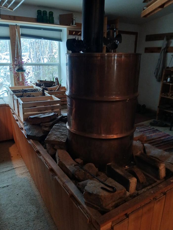
Peter Chauffeur wrote:Choosing a 100 lb. Propane cylinder for the bell was the engineering product of choice as their thickness and quality of metal are designed to take massive amounts of heat while containing propane and preventing a rupture leading to a BLEVE (if the pressure valve fails)
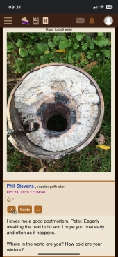
Peter Chauffeur wrote:I will include a picture of the inside of my ceramic riser shortly after shutdown looking down the 3/4” threaded “scully fitting” that used to hold the brass valve. The glowing red area is where the horizontal burn tunnel hits the vertical ceramic riser.
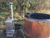
My design is solid, takes a bit of craftsmanship and safety engineering so I can leave it to heat my home and hot tub while I’m out enjoying riding my horse in the Great Canadian pacific northwest!
Build it right the first time. I strongly suggest you get an empty , devolved 100 lb propane cylinder for and replace you re-engineered oil can for safety’s sake.
Be safe and be warm.
 3
3
 3
3
 1
1

Self-Proclaimed Renaissance Man and Gizmologist.
4
Self-Proclaimed Renaissance Man and Gizmologist.
2
1
Self-Proclaimed Renaissance Man and Gizmologist.

|
moose poop looks like football shaped elk poop. About the size of this tiny ad:
It's a bit like "run away to the circus" but with gardening
https://wheaton-labs.com/bootcamp
|