• Post Reply Bookmark Topic Watch Topic
  • New Topic
permaculture forums growies critters building homesteading energy monies kitchen purity ungarbage community wilderness fiber arts art permaculture artisans regional education skip experiences global resources cider press projects digital market permies.com pie forums private forums all forums
this forum made possible by our volunteer staff, including ...
master stewards:
  • Devaka Cooray
  • Carla Burke
  • John F Dean
  • Nancy Reading
  • Timothy Norton
  • r ranson
stewards:
  • Jay Angler
  • Pearl Sutton
  • paul wheaton
master gardeners:
  • Christopher Weeks
  • M Ljin
gardeners:
  • thomas rubino
  • Eino Kenttä
  • Jeremy VanGelder

Airframe Construction Shorty Core

 
gardener
Posts: 1148
Location: +52° 1' 47.40", +4° 22' 57.80"
565
woodworking rocket stoves wood heat
  • Likes 5
  • Mark post as helpful
  • send pies
    Number of slices to send:
    Optional 'thank-you' note:
  • Quote
  • Report post to moderator
Gents, I think I've spotted a deviation from the drawings I've sent earlier. According to these drawings, the air frame should be mounted in front of walls, ceiling and floor of the firebox. What you've constructed is different in the sense that the frame is resting on top of the firebox floor instead of mounted in front. By doing that, the threshold to keep the ashes in is higher and the door the same size smaller (lower). As long as the air slots in the frame are according to specs, no harm is done, one would say. But... there's another thing, the air frame, although air cooled, will get awfully hot. With more steel exposed to the fire, it will get even hotter. Resulting in a greater expansion of the air in there.

What I've seen with the DSR3, too great expansion will lead to more volume, to such an extent that the fire won't get enough oxygen anymore. Combustion quality will suffer from that effect, no doubt about that. Now it is a fact that the DSR3 construction was/is different from the Shorty's.
It could be that in this case the effect isn't that great, but I wouldn't bet on it.

Just to let you know there might be a pitfall in the vicinity.
 
Posts: 360
Location: North East Iowa, USA
106
  • Likes 6
  • Mark post as helpful
  • send pies
    Number of slices to send:
    Optional 'thank-you' note:
  • Quote
  • Report post to moderator

Peter van den Berg wrote:Gents, I think I've spotted a deviation from the drawings I've sent earlier. According to these drawings, the air frame should be mounted in front of walls, ceiling and floor of the firebox. What you've constructed is different in the sense that the frame is resting on top of the firebox floor instead of mounted in front. By doing that, the threshold to keep the ashes in is higher and the door the same size smaller (lower). As long as the air slots in the frame are according to specs, no harm is done, one would say. But... there's another thing, the air frame, although air cooled, will get awfully hot. With more steel exposed to the fire, it will get even hotter. Resulting in a greater expansion of the air in there.

What I've seen with the DSR3, too great expansion will lead to more volume, to such an extent that the fire won't get enough oxygen anymore. Combustion quality will suffer from that effect, no doubt about that. Now it is a fact that the DSR3 construction was/is different from the Shorty's.
It could be that in this case the effect isn't that great, but I wouldn't bet on it.

Just to let you know there might be a pitfall in the vicinity.


I will have to look at this again and is probably my fault in interpretation of the drawings. With that being said, and with this already being built, if we took a Insulated Fire brick split, exactly the height of this lower frame and just set it inside the fire box. (on the fire box floor)   We would hardly know it was there, it would repel the heat from the frame, and would only loose a fraction of space?  Would this be a simple cure for the threat of to much expansion of inflowing air?  Just thinking out loud, and it would sure let the build go on nicely.

Scott
 
master rocket scientist
Posts: 6895
Location: latitude 47 N.W. montana zone 6A
3849
cat pig rocket stoves
  • Likes 6
  • Mark post as helpful
  • send pies
    Number of slices to send:
    Optional 'thank-you' note:
  • Quote
  • Report post to moderator
Good Day, Peter;
Thank you for spotting this.
Currently, we have not gasketed any of the metal.
The plan is to place Superwool between the airframe and the bricks, on the face of the core and where it sits on the floor.

If I cut the floor bricks back even with the walls so the airframe is exposed on the bottom side, would that be a better solution than gasket?


rocket scientist
Posts: 202
Location: Sangre de Cristo Mountains, CO - Lat 38°14' - Zone 5b
172
hunting earthworks solar wood heat rocket stoves homestead
  • Likes 7
  • Mark post as helpful
  • send pies
    Number of slices to send:
    Optional 'thank-you' note:
  • Quote
  • Report post to moderator

Peter van den Berg wrote:Gents, I think I've spotted a deviation from the drawings I've sent earlier. According to these drawings, the air frame should be mounted in front of walls, ceiling and floor of the firebox.


Peter, looking at one of the pictures from your Compact Core Development post (picture pasted below) it appears the door frame air intake is in line with the face of the firebox floor brick. Am I interpreting this correctly? So, there effectively is no threshold for retaining ash (or perhaps a very low threshold)?

Peter van den Berg wrote:But... there's another thing, the air frame, although air cooled, will get awfully hot. With more steel exposed to the fire, it will get even hotter. Resulting in a greater expansion of the air in there.


Can you explain a little further the reason why the expansion of the air will decrease the oxygen. This is of critical interest to me. As you are aware, I live at 8,000' and consequently have to make adjustments to air intakes to account for lower oxygen concentration.
IMG_20231129_113857-(Medium).jpg
[Thumbnail for IMG_20231129_113857-(Medium).jpg]
 
Peter van den Berg
gardener
Posts: 1148
Location: +52° 1' 47.40", +4° 22' 57.80"
565
woodworking rocket stoves wood heat
  • Likes 6
  • Mark post as helpful
  • send pies
    Number of slices to send:
    Optional 'thank-you' note:
  • Quote
  • Report post to moderator

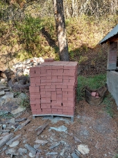
thomas rubino wrote:If I cut the floor bricks back even with the walls so the airframe is exposed on the bottom side, would that be a better solution than gasket?


Scott's solution might be sufficient. You might have some split firebrick leftovers, one of those to shield the lower bottom tube from the inside plus a gasket between steel and brick looks like being good enough. The slanted bricks on the inside plus the expected bed of ashes will shield even more.
 
Scott Weinberg
Posts: 360
Location: North East Iowa, USA
106
  • Likes 7
  • Mark post as helpful
  • send pies
    Number of slices to send:
    Optional 'thank-you' note:
  • Quote
  • Report post to moderator
After yesterdays unclear air flow path photo's  I decided to try to show it without tube radius edges, so hopefully it will show that.  Plus barely seen is one Insulated Fire brick split, Just inside the door air frame, it is slightly not tall enough , but one can work around that with scrap pieces and slightly short on the ends, but overall a nice fit for one full size split american sized fire brick--  4.5 x 9 x 1.25" thick

shorty-with-base-bricks-air-flow-close-and-protective-fire-brick.JPG
Showing general airflow expected, less doors and protective inside fire brick
 
Peter van den Berg
gardener
Posts: 1148
Location: +52° 1' 47.40", +4° 22' 57.80"
565
woodworking rocket stoves wood heat
  • Likes 9
  • Mark post as helpful
  • send pies
    Number of slices to send:
    Optional 'thank-you' note:
  • Quote
  • Report post to moderator

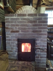
Glenn Littman wrote:Peter, looking at one of the pictures from your Compact Core Development post (picture pasted below) it appears the door frame air intake is in line with the face of the firebox floor brick. Am I interpreting this correctly? So, there effectively is no threshold for retaining ash (or perhaps a very low threshold)?


Hi Glenn, your interpretation is a bit off. In reality, the space below the threshold is filled up almost completely with ash. The development model happens to be a 5 inch(ish) system and the threshold height (just measured) is 35 mil (1.38"). So the ash bed can't be much higher before it'll come out as soon as the door is opened. Interestingly, the floor of both the riser box and the port are practically without ash. Blown away by the higher velocity, that is.

Glenn Littman wrote:Can you explain a little further the reason why the expansion of the air will decrease the oxygen. This is of critical interest to me. As you are aware, I live at 8,000' and consequently have to make adjustments to air intakes to account for lower oxygen concentration.


I'll try to paint a picture of what I *think* is happening, I am unable to refer to any scientific proof whatsoever, just my idea of what might happens aerodynamically. Imagine the ducts that carry the air to the firebox' innards are straight and just the same size everywhere. The inlet and outlet sides the same as the ducts itself, that's simple. Steer air through it, sucked in by the draw of the chimney and the same that goes in also comes out.

Now complicate the picture a bit, the duct isn't straight. So the air stream need to go through several bends in order to arrive where we want it. Assuming the chimney draw is still the same, we need to compensate for the friction of the bends just to make sure the correct amount of oxygen arrives where it should be. That's why the bottom member of the air frame is much larger than the rest of it.

Now complicate matters even further. The temperature of the air is at room level but the duct isn't, far from that. So the air will heat up quite a bit and as such will expand. Now it becomes very, very interesting, the ducts and inlet as well as outlet openings are still the same size. The volume of air that's at 68 degrees F  while volume =1 liter is converted inside the duct to 662 F with volume of 2.1 liters. So there's more volume that need to go through the bends and ducts, and due to their higher speed also poses more friction to the stream.

Now, when the temperature and therefore the volume is risen even more: at 800 F the volume will be 2.4 times as compared to the inlet side. Assuming the chimney pull is still the same and the carrying capacity of the bended duct has an upper limit (which sounds reasonable to me), the air velocity at the inlet will slow down. Resulting in less air  and thus, inevitably, less oxygen will be pulled in.

The situation is of course much more complicated and a single duct with bends is a too simple picture. But exactly this is what happened (in my opinion) during development of the commercial version of the DSR3. As soon as I shortened the air path significantly, the core behaved itself again. The lesson I learned from this: getting the combustion air at really, really high temperatures before it is fed to the fire might result in incomplete combustion. The more because the expanded air stream will blow at the fire quite fiercely so lots of combustable gases are formed.
My conclusion: heating up the combustion air, OK, but keep it modest, 200 degrees F sounds enough to me, the expansion factor will be around 1.5 then.

An example: a guy from Begium built an 8" DSR3 system, upscaled from my 5" development model. The capital mistake he made was to use the same size air duct as I did. The thing ran very well, provided the door was open a generous crack all the time. At the moment the door was closed, the fire slowed down to such an extent that the afterburner function popped off, spewing thick black smoke from the chimney.

Now heater cores at high altitude: just make the inlet side a bit wider (40% of system csa) and keep the steel air frame out of the highest heat where you can. In general, oxygen content of air is the same everywhere on earth, being 21%. At higher altitudes, the air is thinner so in order to get enough oxygen inside more volume need to be pulled in. Looks a bit like the situation above although not as exaggerated.

Quite a long answer, hope this all makes sense.
 
Glenn Littman
rocket scientist
Posts: 202
Location: Sangre de Cristo Mountains, CO - Lat 38°14' - Zone 5b
172
hunting earthworks solar wood heat rocket stoves homestead
  • Likes 9
  • Mark post as helpful
  • send pies
    Number of slices to send:
    Optional 'thank-you' note:
  • Quote
  • Report post to moderator
Tom, apologies for the diversion of your airframe reporting. I think this is highly pertinent though and that you'll be in favor of the discussion... at least I hope so.

Peter van den Berg wrote:Quite a long answer, hope this all makes sense.


This makes total sense Peter and thank you for painting the picture in a clear manner. This may not be a direct comparison but it brings to mind the race car development work back in the '80's and adding an intercooler to a turbocharged engine to improve the air density going into the combustion chambers.

So it would make sense to keep the air as cool as possible as it approaches the firebox. Do you feel your current door frame/air intake design is sufficiently managing the temperature of the air? Would it make sense to continue development to reduce the air heating further? If so, there are two things I can think of to aid in that goal.

A piece of refractory could be used as the threshold to retain the ash and shield the surface of the steel currently acting as the threshold. It would need to be thick enough to not crumble over time or designed is such a way that it can survive for a reasonable period of time if care is used in loading wood and easily replaced as needed.

The other thought is something I learned of from a very long and technical discussion over at Donkey's titled; Why Firebricks/Refractories Fail https://donkey32.proboards.com/thread/3909/firebricks-refractories-fail-silica-flux. Doing some further investigation into these products I found some folks that build forges and through testing were seeing up to about 200 degree cooler temperatures in the forge linings when applying these type coatings and the coatings can be used on refractory as well as steel. There is a list of commercial refractory coatings given and I had used one of these products in the core of my previous build called ITC-100HT. I had no way to run an actual test with or without but I'm now thinking to perhaps apply some to the inside of my door after taking some repeated temperature readings for a before and after test. If the product performs as claimed it could be used on the airframe to further reduce the incoming air temperature.

My interest is perhaps greater than most given my unique situation of lower air density a 8,000', but there is still the general air flow dynamics that all batch rockets will deal with at any elevation.
 
thomas rubino
master rocket scientist
Posts: 6895
Location: latitude 47 N.W. montana zone 6A
3849
cat pig rocket stoves
  • Likes 12
  • Mark post as helpful
  • send pies
    Number of slices to send:
    Optional 'thank-you' note:
  • Quote
  • Report post to moderator
Yesterday after reading Peter's observation that our door was higher than he intended it to be, and with the possibility of overheating the incoming air.
Scott suggested placing an insulated split firebrick over the back of the air intake to shield it from the heat.
Gerry and I went out to the shop and looked things over.
I cut a full-size insulated brick into a split brick and placed it in the firebox.
Between the brick and any ash buildup, the airframe would be insulated and the problem avoided.
Except for having a 5" threshold at the door of the stove.
Peter intended for there to be a 2 3/8" threshold.

After some discussion, we hopped in the Subaru and off to the Pacific Steel store in Idaho.
I purchased a 1' piece of 2.5" tubing bringing the required amount of tubing needed to build the airframe to six feet.

Today, we cut our brand-new airframe into two pieces and added a 2.5" extension on each side.
This lowered the entire airbox, leaving only 2.5" exposed to the inside of the firebox.
I intend to use a piece of 1" Superwool banked with ash to insulate the upper portion that remains exposed.
I removed the front two firebricks from the floor, cutting one to length and the other was moved forward with 1/2" of Superwool to fill the gap.
The lower, angle iron frame was 1/4" too small for the airframe to sit inside of.
I cut off the vertical legs of all three pieces leaving a nice flat platform for the airframe to sit on, Superwool will be used on all faces.
We had to relocate the two lower tabs for the all-thread to line up.
With some sanding and a coat of high-heat black paint, it will look outstanding

This project took a whole day plus the costs of metal and fuel.
It was time and money well spent, to make my new stove as good as its designer intended.
If I follow a proven design then I will get proven results.


20240511_102359.jpg
cutting my "new" airframe in half
20240511_104250_resized.jpg
Grinding it smooth
Grinding it smooth
20240511_120203.jpg
Keeping things square
20240511_120227.jpg
adding the extensions
20240511_134512_resized.jpg
getting ready to add the new tab
20240511_121755.jpg
Floor bricks cut to length
20240511_141102.jpg
Test fit , base angles cut flat.
20240511_151834_resized.jpg
all welded up
all welded up
20240511_151910_resized.jpg
[Thumbnail for 20240511_151910_resized.jpg]
20240511_160758.jpg
playing with bricks
playing with bricks
 
Peter van den Berg
gardener
Posts: 1148
Location: +52° 1' 47.40", +4° 22' 57.80"
565
woodworking rocket stoves wood heat
  • Likes 9
  • Mark post as helpful
  • send pies
    Number of slices to send:
    Optional 'thank-you' note:
  • Quote
  • Report post to moderator
Looks good, in proportion now. Thanks gents, feels much better.
Other suggestion for the tension frame: it might be better to extent the angle iron at the back to the top of the riser box. With two short pieces on top of the firebox and two short all-threads each side, the complete core will be within the frame then.

At the front, I would consider to cut off the third airframe support, the one beside the center. It isn't required structurally and it looks oddly a-symmetrical now.

Please go on, I am curious how it'll turn out.
 
Rocket Scientist
Posts: 1826
Location: Kaslo, BC
530
building solar woodworking rocket stoves wood heat greening the desert
  • Likes 10
  • Mark post as helpful
  • send pies
    Number of slices to send:
    Optional 'thank-you' note:
  • Quote
  • Report post to moderator
Seeing as how this shorty core does not have the need for a floor channel brings up the much higher risk of unintentionally plugging up the port with wood shoved too far back or from a falling piece of coal.

An idea came up....Perhaps an upside down U shaped piece of metal rod (approximately the width and height of the firebox port) could be mounted on a plate steel base and positioned about an inch or so before the port? The plate would be sized the same dimensions as the inside floor so it wouldn't move around and (if needed) a horizontal top spacer butting up against the top port brick to keep it from tilting.
Shouldn't interfere with gas flow any more than a stub would.
Yes, metal is going to spall, but still perhaps last long enough to warrant its advantages.
Any thoughts?
 
I love a woman who dresses in stainless steel ... and carries tiny ads:
The new gardening playing cards kickstarter is now live!
https://www.kickstarter.com/projects/paulwheaton/garden-cards
reply
    Bookmark Topic Watch Topic
  • New Topic