|

|

|

|

|

|
|
|
|
|
|
|
|

|

|

|

|

|
 3
3


Skill verified by gir bot") 3
4
3
4
Eric Hanson wrote:Ok, I will try to explain what is going on in this (mess) picture!
..................................
I still have a few things to tidy up. I need to shorten some cables and tie other cables together to make things look better, but I think it is coming along.
Thoughts?
Eric
“The most important decision we make is whether we believe we live in a friendly or hostile universe.”― Albert Einstein
2
Allen Jackson wrote:Amazon actually sells parallel compatible versions of the JK BMS, if you are wanting to do combo series/parallel battery packs
https://www.amazon.com/gp/aw/d/B0FPCZS56M
![[Thumbnail for JKBMS.jpg]](/t/274663/a/287286/JKBMS.jpg "Filename: JKBMS.jpg
Description:")
“The most important decision we make is whether we believe we live in a friendly or hostile universe.”― Albert Einstein
3
John Weiland wrote:Eric, I may have missed it in your build description, but do you have plastic/ABS separation sheets between each adjacent cell? I just received 4 EVE 100 Ah cells that will fit nicely in an ammo-box build but need to confirm the need or not for dividers as has been mentioned elsewhere on internet descriptions. Thanks!
4
![[Thumbnail for EVEcells105Ah.jpg]](/t/274663/a/287861/EVEcells105Ah.jpg "Filename: EVEcells105Ah.jpg
Description:")
![[Thumbnail for BuildComponents.jpg]](/t/274663/a/287862/BuildComponents.jpg "Filename: BuildComponents.jpg
Description:")
![[Thumbnail for Bars-Bolts.jpg]](/t/274663/a/287863/Bars-Bolts.jpg "Filename: Bars-Bolts.jpg
Description:")
“The most important decision we make is whether we believe we live in a friendly or hostile universe.”― Albert Einstein
4
John Weiland wrote:Thanks to the OP and others for continuing this helpful thread.
I finally have the components to get started with an initial build of a 12V LiFePO4 battery. This will primarily be for stand-alone applications....running small household lamps, powering remote trail and surveillance cameras, operating emergency back-up for a propane furnace (through inverter), etc. We will see how this goes and then decide if continued builds are in order or if the price for fully-assembled commercial batteries becomes too low to justify continued DIY on this front.
Although many battery cell sets come with the hardware for cell connection, mine did not so this needed to be ordered separately. In addition, even though the documentation claimed that the terminal threads were M6, they clearly are M4 which I could not find locally. So these had to be ordered online also. A quick check of the cells has them all showing 3.20V. The JK BMS purchased is shown in a previous post above and is enabled for battery heating as well as Bluetooth monitoring of battery/cell status and BMS configuration. I've downloaded the phone app for this but need to get all connections set up before it will recognize the BMS. I don't know how much 'programming' is needed for battery set-up.....hoping this is not terribly difficult. Also, as I'm only using a subset of the BMS monitoring/balancing wires for a 4-cell build, do I really need to remove the additional wires or can these be isolated with insulators and wrapped out of the way of the other components? I'm glad to see this comes with an on/off switch although I have to ask, with so many LiFePO4 batteries available that do NOT have on/off switches, what is the main point of having one?...battery drain in storage?...safety?
Anyway, hoping to learn here from Eric's build and other comments...fun project and hope all goes well with it! Open to questions and further commentary....
Edited to add: If anyone knows of a good step-by-step YouTube video (Will Prowse?...others?) that they can recommend for simple LiFePO4 builds, I would be grateful. Thanks!....


 5
5
Some places need to be wild
4
4

 with an inverter, but the same BMS as the 12 Vdc one") 4
4
![[Thumbnail for 20260423_140311.jpg]](/t/274663/a/287959/20260423_140311.jpg "Filename: 20260423_140311.jpg
Description:") 4
4
Allen Jackson wrote:............... so yeah, put some non-conductive protection between the cells!
“The most important decision we make is whether we believe we live in a friendly or hostile universe.”― Albert Einstein
2
 3
3
![[Thumbnail for boxwidth.jpg]](/t/274663/a/287969/boxwidth.jpg "Filename: boxwidth.jpg
Description:")
![[Thumbnail for RecessedConnector.jpg]](/t/274663/a/287970/RecessedConnector.jpg "Filename: RecessedConnector.jpg
Description:")
“The most important decision we make is whether we believe we live in a friendly or hostile universe.”― Albert Einstein
5

 5
5
Some places need to be wild
5
4
Some places need to be wild
4
Some places need to be wild
4
![[Thumbnail for BatteryQuickConnect.jpg]](/t/274663/a/288002/BatteryQuickConnect.jpg "Filename: BatteryQuickConnect.jpg
Description:")
“The most important decision we make is whether we believe we live in a friendly or hostile universe.”― Albert Einstein
4
Eric Hanson wrote:I am using those 30/45 amp connectors. When I get them in right, they are great. But I am still learning and I put them in upside down more often than I would like to admit.
“The most important decision we make is whether we believe we live in a friendly or hostile universe.”― Albert Einstein
4
Some places need to be wild
6
Eric Hanson wrote:Just to reiterate, this was originally going to be an 80 AH build, but the 80 AH cells became unavailable. The 100 AH cells fit, though it gets a little tight.
A note on ordering cells: From now on, I will just buy the Amazon ones. I thought I was going to save some money by purchasing direct overseas. Bad choice. Shipping was outrageous, and this was not clearly indicated until the item was in transit which tool weeks. I thought they lost the cells so I bought another set of cells and they did not show up so I broke down and bought some from Amazon. And all three sets showed up on the same day!
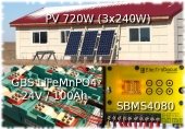
I guess I have a 100A, 24v, 2400Ah system in my future!
Eric
4
John Weiland wrote:I was wondering why those Anderson connectors looked familiar.....then realized it's the plug and receptacle combination for my EZGO golf cart! The amps delivered when charging is ~15 - 20 so this would make sense for a low amp battery build as well, even as they may be able to tolerate higher amps at low voltage.
Which also brings me to my rationale for the desired battery box receptacle (+ and - terminals)..... I'm somewhat enamored with the cable-end connectors shown below, actually having replaced the standard lead cable terminals on cars, tractors, lawn equipment, generators, etc. with these. My intent is to use a standard battery post that screws into the M6 female threads on the receptable of the new build, then use the quick-connect cable ends shown to connect the desired device to the battery...
4
Allen Jackson wrote:
.........
How's your metal working skills?
..... the most common metric bolt in American automotive fasteners is the M6 x 1.0 mm.
![[Thumbnail for M6recessed.jpg]](/t/274663/a/288045/M6recessed.jpg "Filename: M6recessed.jpg
Description:")
“The most important decision we make is whether we believe we live in a friendly or hostile universe.”― Albert Einstein
5

") 5
5
John Weiland wrote:My metal working skills are pretty non-existent, unless sharpening an axe head and lawnmower blade counts..??

I'm going to try the item shown below and see if (a) I can find some sort of washer that would allow pass-through of the threaded insert just up to the 11.6 mm flange, (b) I can find some sort of coarse-threaded nut to spin onto the outer threads of that bolt, (c) the inner M6 threads will match the pitch (1.0) of the bolts and battery posts that I have on hand, and (d) the hex key portion of the insert is not so deep that it prohibits adequate access of the inner M6 threads from the top of the insert. The end result would be a fixture on top of the battery case that is a washer with an M6 threaded female insert on the outside of the case and inner-case surface threads on which to attach the cabling. (hoping that's all clear and understandable...) Even if I can't find a perfect matching nut for those coarse surface threads of that insert, I may be able to use extra washers or bushings to spin on a nut just enough to provide good contact between the battery cable and that post.
Weather has been decent lately so outdoor chores have taken priority. With rain moving in, hoping to get on with cell-wrapping and BMS wire attachments in a few days. Those balancing wires did not come with eyes attached, so need to crimp those on before starting. This brings up a quick question: So much discussion about making sure the cells are balanced between them before assembly---but if the BMS provides "active balancing", why wouldn't this function serve to balance at least slightly imbalanced cells after the first few charge/discharge cycles? Thanks....looking forward to finally diving in!
Edit: Now thinking,....probably makes more sense to put case-exterior posts on the *side* of the box instead of top, yes? That way am not opening a lid (when needed) that itself is attached to cables...??
5
![[Thumbnail for 1000011228.jpg]](/t/274663/a/288066/1000011228.jpg "Filename: 1000011228.jpg
Description:") 3
3
![[Thumbnail for 1000011246.jpg]](/t/274663/a/288149/1000011246.jpg "Filename: 1000011246.jpg
Description:") 2
2
Allen Jackson wrote:............I think it will still be over a week to deplete the battery...
“The most important decision we make is whether we believe we live in a friendly or hostile universe.”― Albert Einstein
3
 5
5
Some places need to be wild
3
Some places need to be wild
2
4
“The most important decision we make is whether we believe we live in a friendly or hostile universe.”― Albert Einstein
4
John Weiland wrote:Quick question on how other have dealt with the balancing wire length. My BMS was shipped with balancing wires over 2 ft in length, much longer than I would need for the build. Allen J. mentioned just coiling up *unused* wires in a safe and compact manner in case the BMS would be used for a larger build in the future. I'm inclined to also coil up, for space reasons and to preserve the wire length, the wires used actively in the balancing of the cells, rather than trim the wires for a 'cleaner' build. Is there any reason why it's recommended to keep the active wires shorter?....or could I keep the wires long and just wrap them up the box as cleanly as possible after making the connections to the cell terminals? Thanks!.....
4


 4
4
![[Thumbnail for 1000011265.jpg]](/t/274663/a/288277/1000011265.jpg "Filename: 1000011265.jpg
Description: 2/0 welding cable")

 4
4
Some places need to be wild
4
“The most important decision we make is whether we believe we live in a friendly or hostile universe.”― Albert Einstein

|
It's a beautiful day in this neighborhood - Fred Rogers. Tiny ad:
change the world (for the better) with hands on permaculture
https://wheaton-labs.com/bootcamp
|