|

|

|

|

|

|
|
|
|
|
|
|
|
|
|

|

|

|

|


"Never doubt that a small group of thoughtful, committed citizens can change the world; indeed, it's the only thing that ever has."-Margaret Mead "The only thing worse than being blind, is having sight but no vision."-Helen Keller
 1
1
best regards, Byron
1
regards, Peter
 I shall endeavor to view all and get back to ya if I need more info.
 "Never doubt that a small group of thoughtful, committed citizens can change the world; indeed, it's the only thing that ever has."-Margaret Mead "The only thing worse than being blind, is having sight but no vision."-Helen Keller
"Never doubt that a small group of thoughtful, committed citizens can change the world; indeed, it's the only thing that ever has."-Margaret Mead "The only thing worse than being blind, is having sight but no vision."-Helen Keller


 6
6
![[Thumbnail for RMH-rebuild_144.JPG]](/t/60402/a/45310/RMH-rebuild_144.JPG "Filename: RMH-rebuild_144.JPG
Description: P channel in a J tube")
For all your Montana Masonry Heater parts (also known as) Rocket Mass heater parts.
Visit me at
dragontechrmh.com Once you go brick you will never go back!
"Never doubt that a small group of thoughtful, committed citizens can change the world; indeed, it's the only thing that ever has."-Margaret Mead "The only thing worse than being blind, is having sight but no vision."-Helen Keller
2
![[Thumbnail for DSCN4014.JPG]](/t/60402/a/45318/DSCN4014.JPG "Filename: DSCN4014.JPG
Description:")
For all your Montana Masonry Heater parts (also known as) Rocket Mass heater parts.
Visit me at
dragontechrmh.com Once you go brick you will never go back!
"Never doubt that a small group of thoughtful, committed citizens can change the world; indeed, it's the only thing that ever has."-Margaret Mead "The only thing worse than being blind, is having sight but no vision."-Helen Keller
"Never doubt that a small group of thoughtful, committed citizens can change the world; indeed, it's the only thing that ever has."-Margaret Mead "The only thing worse than being blind, is having sight but no vision."-Helen Keller
"Never doubt that a small group of thoughtful, committed citizens can change the world; indeed, it's the only thing that ever has."-Margaret Mead "The only thing worse than being blind, is having sight but no vision."-Helen Keller
1
Roberto pokachinni wrote:
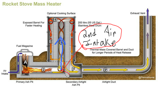
Why are some of the designs adding the 2nd air supply near the end of the burn tunnel and others at the beginning? Are there differences? Why one or the other?
best regards, Byron
1
regards, Peter
2
For all your Montana Masonry Heater parts (also known as) Rocket Mass heater parts.
Visit me at
dragontechrmh.com Once you go brick you will never go back!
So, Peter, is this what you personally do with your batch box. Does the burn tunnel ceiling slope for it's full length, or just near the end. Is the bluff just a slight protrusion descending from the ceiling or is the bluff the exterior wall of the heat riser that the flow slams into and thus has to descend in order to enter the heat riser. When I was reading about trip wires on the links I was given above in this thread, I read and visualized a groove cut into part of the burn tunnel. So, in relation to that last thought, is the bluff a divet or groove in the ceiling that breaks the boundary layer, the sharp corner being an indent rather than a block of protruding substance? I remember seeing on of your sketch ups that had multiple angles and slopes, but that doesn't seem to quite match what you are saying here... I will have to review those sites in light of the Thermodynamics Crash Course. I can't say that I fully understand all of the course, by the way. He mentions cD a few times, specifically near the end, but did not define it from what I could find. Perhaps I need a big yellow no name brand: Thermodynamic Crash Course for Dummies.The burn tunnel ceiling is ramping down slightly to end in a sharp corner or "bluff", breaking up the boundary layer along the ceiling.
"Never doubt that a small group of thoughtful, committed citizens can change the world; indeed, it's the only thing that ever has."-Margaret Mead "The only thing worse than being blind, is having sight but no vision."-Helen Keller
Thanks for your help Byron, and for the link.Building your first RMH? This book will be invaluable in saving you time, labor, and money:
https://permies.com/t/57365/rocket-mass-heaters/Rocket-Mass-Heater-Builder-Guide
"Never doubt that a small group of thoughtful, committed citizens can change the world; indeed, it's the only thing that ever has."-Margaret Mead "The only thing worse than being blind, is having sight but no vision."-Helen Keller
Thanks for Clarifying Thomas.that little fan to push air with a cold very wet core.
"Never doubt that a small group of thoughtful, committed citizens can change the world; indeed, it's the only thing that ever has."-Margaret Mead "The only thing worse than being blind, is having sight but no vision."-Helen Keller
2
Roberto pokachinni wrote:So, Peter, is this what you personally do with your batch box. Does the burn tunnel ceiling slope for it's full length, or just near the end.
regards, Peter
2
this was a much better read the second time around, particularly after the crash course in Thermodynamics!Please read the first and second page of this thread, it will explain a lot.
Perfect explanation, particularly with all the images in Peter's Donkey thread.The tripwire is only used with a J-tube configuration. In a firebrick construction, one brick (usually the second from the feed tube) will be ground down at its ends so it drops 1/4" or so below the rest, and the bottom face ground to a slope that meets the first brick smoothly, ramps down from the ceiling, and leaves a sharp trailing edge where it meets the third brick.
For a cast J-tube, this shape is just molded into the ceiling.
"Never doubt that a small group of thoughtful, committed citizens can change the world; indeed, it's the only thing that ever has."-Margaret Mead "The only thing worse than being blind, is having sight but no vision."-Helen Keller

| I agree. Here's the link: http://stoves2.com |