

• Post Reply Bookmark Topic Watch Topic
  • New Topic
permaculture forums growies critters building homesteading energy monies kitchen purity ungarbage community wilderness fiber arts art permaculture artisans regional education skip experiences global resources cider press projects digital market permies.com pie forums private forums all forums
this forum made possible by our volunteer staff, including ...
master stewards:
  • Carla Burke
  • Nancy Reading
  • John F Dean
  • r ransom
  • Jay Angler
  • Timothy Norton
stewards:
  • paul wheaton
  • Tereza Okava
  • Nicole Alderman
master gardeners:
  • M Ljin
  • Christopher Weeks
gardeners:
  • Jeremy VanGelder
  • thomas rubino
  • Megan Palmer

Building 100 AH LiFePo4 Battery Box

 
Posts: 137
26
  • Likes 4
  • Mark post as helpful
  • send pies
    Number of slices to send:
    Optional 'thank-you' note:
  • Quote
  • Report post to moderator
A 17-18 Vdc solar panel is just barely enough to charge a 12 Vdc battery, and even then, it's going to be (maybe painfully) slow. Depending on how fast you need to use the system, you may find you need/want more power or need more charging speed.

It may help to convert everything to the same units?

100 Ah 12.8 Vdc battery = backup 1280 volt-amp-hours, which = 1280 watt-hours, which = 1.28 KWh. A 100 watt panel in ideal conditions would need nearly 13 hours to fully charge that battery from 0.

Your probably not in Death Valley, California, or a desert in southern Arizona, so you probably won't have access to "ideal" solar conditions, and may only get 50% of the nameplate rating from your panel, which will mean it takes almost 26 hours of sunlight to charge your battery... How much patience do you have??
 
pollinator
Posts: 2913
Location: RRV of da Nort, USA
896
  • Likes 8
  • Mark post as helpful
  • send pies
    Number of slices to send:
    Optional 'thank-you' note:
  • Quote
  • Report post to moderator

Allen Jackson wrote:...... it takes almost 26 hours of sunlight to charge your battery... How much patience do you have??


:-)..Ha!   This will be a good test of my set-up, but also just to say that I don't at this point have plans on needing this particular battery that frequently nor with deep discharging.  So having it parked on a panel/controller for several days without use is what I anticipate for now.  That said, I keep my eyes grazing overFacebook Marketplace for used panel offerings of which there are several over 300W.

But on to the show so far.....

Below are some photos showing the status of the build.  It's pretty crude, but working and ready for a load testing today.  I probably will take one or both of a 1500W modified sine wave inverter or the 700W pure sine wave inverter out for a test drive with the battery.  I may end up tripping the shut off on either the inverter or he battery with trying to power an old Craftsman circular saw, but one step at a time to see what is possible.....will start out slow with smaller power tools and work upward in power draw from there.

So far the 'cabinetry' metal inserts are working as desired:  Holes drilled into the lid of the case were readily matched with the insert to ensure that the coarse threads of the insert had good 'bite' on the casing.  Using a hex key wrench, I was able to get the insert pretty flush with the casing surface.  That said, I also have on hand some nylon washers that I could run the insert through which may give even a more firm fit....if so, I would just epoxy the washer to the case so that it would be a fixed receptacle for the insert.  The two photos shown at top are the insert just being placed in the hole and then the insert seated in the hole. Because these inserts were ordered in a 25 mm length, they stick through the lid far enough so that the bottom of the insert can readily attach to the inner battery cable (stranded  4 AWG).  Since the hole inside of the insert is M8 threaded, the cables are attached to the insert via an M8 flange bolt that holds the cable ring loop down onto the edge of the insert bottom.  With the lid closed, the insert provides M8 inner threads for attaching devices/loads to the battery.  This can either be done using M8 bolts, but also as shown is an M8 threaded battery post.  As noted in an earlier entry above, this would allow use of standard or quick-attach cable connectors.

Still some mods to go with the build, but I was happy to see that the battery powered up fine and gave proper readings at the insert posts.  I still need to place the on/off button through a hole, probably on the side of the case.  Unfortunately, because of the way that button and lead were assembled, making a hole through which the wire and rear of the button can be threaded may prove difficult, but managable somehow.  Then the retaining nut on that button can be used to hold the button in place.  For now, the temperature sensing leads are running down each side of the cell pack between the case wall and the wall of the outside cell.  I don't really like the tightness of those big 4 AWG cables inside of the box when closing the lid, but like the cramped wiring behind any home light switch or electrical socket, it's all fine if done right and not having to be opened frequently.

Anyway, ..... more to come and hoping I can post some data soon.  Moving manure and cultivating the garden are the priorities of the day, so we'll see where the time goes...  Comments and questions welcomed!
StartingInsert.jpg
[Thumbnail for StartingInsert.jpg]
FinishedInsert.jpg
[Thumbnail for FinishedInsert.jpg]
InsertInside.jpg
[Thumbnail for InsertInside.jpg]
InnerCablesAttached.jpg
[Thumbnail for InnerCablesAttached.jpg]
TestingPost.jpg
[Thumbnail for TestingPost.jpg]
GoodVolts.jpg
[Thumbnail for GoodVolts.jpg]
 
Steward and Man of Many Mushrooms
Posts: 6145
Location: Southern Illinois
1919
transportation cat dog fungi trees building writing rocket stoves woodworking
  • Likes 3
  • Mark post as helpful
  • send pies
    Number of slices to send:
    Optional 'thank-you' note:
  • Quote
  • Report post to moderator
Allen,

How are those Predator folding solar panels working?  I have ambitions some day of having significant solar charging capability and those predator folding panels look like a good bang-for-your-buck options.

Also, I plan on either building my charging controller into my solar panels or have a dedicated charging box w/the charge controller.


Eric
 
Eric Hanson
Steward and Man of Many Mushrooms
Posts: 6145
Location: Southern Illinois
1919
transportation cat dog fungi trees building writing rocket stoves woodworking
  • Likes 2
  • Mark post as helpful
  • send pies
    Number of slices to send:
    Optional 'thank-you' note:
  • Quote
  • Report post to moderator
John, nice construction detail on the lid.  I have always found it difficult to fit wires connecting the lid, which has to move, with wires that should stay put.  Nice compromise.


Eric
 
Allen Jackson
Posts: 137
26
  • Likes 6
  • Mark post as helpful
  • send pies
    Number of slices to send:
    Optional 'thank-you' note:
  • Quote
  • Report post to moderator

Eric Hanson wrote:Allen,

How are those Predator folding solar panels working?  I have ambitions some day of having significant solar charging capability and those predator folding panels look like a good bang-for-your-buck options.

Also, I plan on either building my charging controller into my solar panels or have a dedicated charging box w/the charge controller.
Eric


The big benefit of the Predator 200 watt solar panels, is they are foldable, so they are extremely portable. They fit in the back of nearly any vehicle.

If you are truly interested in solar power as in stationary/fixed solar, go get REAL solar panels, because the cost/watt is much better than the portable ones.
 
Eric Hanson
Steward and Man of Many Mushrooms
Posts: 6145
Location: Southern Illinois
1919
transportation cat dog fungi trees building writing rocket stoves woodworking
  • Likes 6
  • Mark post as helpful
  • send pies
    Number of slices to send:
    Optional 'thank-you' note:
  • Quote
  • Report post to moderator
Allen,

While I am terribly interested in solar, I would need a place to mount or if not mount permanently, store.  And you are exactly correct—we pay for portable, but those folding panels look like one of the better options.

For me, this would strictly be an emergency power source/hobby.  If I were more serious, I would definitely mount.

On the other hand, a significant advantage of portable would be during significant wind storms, something of a common event by me.  A panel mounted outside would always be at the mercy of wind and wind-blown debris.  But tucked inside, I could wait out the storm and set up in the clear after the storm.

May 8, 2009, the region had an apocalyptic storm—a derecho—that left the region practically immobile—hundreds of thousands of trees blew down.  I could not get to my home due to fallen trees. My house had no power for 5 days and I was lucky—some were without power for weeks.  I saw telephone poles being placed with giant, tracked atv machines and even helicopters.

External solar panels would have been highly vulnerable in that storm.


Eric


Eric
 
Allen Jackson
Posts: 137
26
  • Likes 2
  • Mark post as helpful
  • send pies
    Number of slices to send:
    Optional 'thank-you' note:
  • Quote
  • Report post to moderator

Eric Hanson wrote:Allen,

While I am terribly interested in solar, I would need a place to mount or if not mount permanently, store.  And you are exactly correct—we pay for portable, but those folding panels look like one of the better options.

For me, this would strictly be an emergency power source/hobby.  If I were more serious, I would definitely mount.

On the other hand, a significant advantage of portable would be during significant wind storms, something of a common event by me.  A panel mounted outside would always be at the mercy of wind and wind-blown debris.  But tucked inside, I could wait out the storm and set up in the clear after the storm.

May 8, 2009, the region had an apocalyptic storm—a derecho—that left the region practically immobile—hundreds of thousands of trees blew down.  I could not get to my home due to fallen trees. My house had no power for 5 days and I was lucky—some were without power for weeks.  I saw telephone poles being placed with giant, tracked atv machines and even helicopters.

External solar panels would have been highly vulnerable in that storm.

Eric


If you're hoping to be able to use a system like this for possible emergency use, then you REALLY don't want to skimp on the internal components that will be major bottlenecks in an emergency.

If you knew that you are going to be without power for 5 days, what would you really want to power? How many KWh would you need to survive in good fashion?  Make a list...
 
Eric Hanson
Steward and Man of Many Mushrooms
Posts: 6145
Location: Southern Illinois
1919
transportation cat dog fungi trees building writing rocket stoves woodworking
  • Likes 4
  • Mark post as helpful
  • send pies
    Number of slices to send:
    Optional 'thank-you' note:
  • Quote
  • Report post to moderator
At the moment this is still a hobby phase with growth potential.  I do have a generator, but being able to be off grid/no gas is a huge plus.

For now, these are mostly for maintaining small electronics.  But if I were to significantly scale up, I would want to be able to power a microwave.


Eric
 
Allen Jackson
Posts: 137
26
  • Likes 4
  • Mark post as helpful
  • send pies
    Number of slices to send:
    Optional 'thank-you' note:
  • Quote
  • Report post to moderator

Eric Hanson wrote:At the moment this is still a hobby phase with growth potential.  I do have a generator, but being able to be off grid/no gas is a huge plus.

For now, these are mostly for maintaining small electronics.  But if I were to significantly scale up, I would want to be able to power a microwave.

Eric


Is the microwave you have in mind, a 1000 watt model? They normally have a label on the back or bottom, listing the electrical specs.

On the plus side, most microwave use is short-term, not for hours at a time, so the total power requirements are lower than a continuous application. A 1000 watt microwave might be in use for no more than 30 minutes a day, so even if you double that for a buffer, that's 1 KWh of energy. That's how much energy a battery system would have to be able to deliver (every day you're wanting to use the appliance).

The "rate" at which the battery system will have to deliver that energy, is 1000 watts per hour, which can be obtained from different sources. For example, a 1000 watt inverter that is a 12 Vdc inverter, it's likely to have an efficiency of 90%, which translates into needing to supply 1100 watts. For a LiFePO4 battery, the nominal voltage is 12.8 Vdc, and 1100 watts (volt-amps=watts) divided by 12.8 Vdc, equals 85.9375 amps. A 100 Ah battery should be capable of that output, but having a 200 or 300 Ah battery gives more of a buffer, in case it can't be recharged for a day or two.  The BMS wouldn't need to be higher capacity than 100 amp, even if the battery was larger than 100 Ah.

Except if the battery is larger, then the BMS might need to be up-sized to match a larger charging system because the charging system should be sized to recharge the entire battery (ideally), but at least sized large enough to cover the daily demand load. If a larger battery is involved, particularly if there could be one or more days of no solar input, it becomes necessary to charge faster than the daily demand load, as one may need to charge 2 or more days worth of energy in a single day.

For example, if one is likely to have 4 hrs of solar to recharge, 1100 watts divided by 4 hrs = 275 watts per hour, which is likely to resemble about 19.5+ amps of charging current, so for that, one will need to use at least a 20 amp charger and enough solar to 400+ watts of solar panels, just to keep the pipe full. IFF one instead has a 200 Ah battery that needs to be charged, the power requirements are doubled, because the 4 hour window is still the same.  550 watts per hour = 40 amps of charging current, and probably 800 watts of solar panels, to be able to keep up, between the clouds and the inefficiency of the panels...

If any component in the chain is unable to hold up its part of the transfer, becomes the bottleneck. A 30-amp charge controller will bottleneck a 40-amp demand, limiting it to about 400 watts (like my Friday test showed), and even more solar panels won't up the power output, and ultimately the goal is to maximize the components - for example, since I already have 1200 watts of solar, I'd like to be able to utilize them, and I should've planned my controller to be able to charge at 1200 watts too... In that case, it would have to be at least a 60-amp charger. That also requires that the BMS and the battery will need to be capable of handling that same level of power, but that part is often easily met by at least a 100 Ah battery and at least a 100 amp BMS, which exceed the minimum requirements.

Other combinations are possible to meet the demands, for example, one can build a 24 Vdc system, not a 12 Vdc system, and as long as the total power demand is met, the microwave will still run, but the bill of materials will be very different.

Do the math before spending the money, and there will be much less wasted resources 🙂
 
Allen Jackson
Posts: 137
26
  • Likes 4
  • Mark post as helpful
  • send pies
    Number of slices to send:
    Optional 'thank-you' note:
  • Quote
  • Report post to moderator
Eric, someone once said "Where you stand on an issue, often depends on where you sit..." I don't remember who said that or where I first heard it, but on the issue of portability, that can look like different things to different people.

These 200 watt  Renogy branded panels are just over 4' long x 30" wide, so they could fit into a closet, or possibly a back seat of a car. For a pickup truck or a minivan, it's a slam dunk, but you get to decide how compact you want or need something to be for your application.

https://www.amazon.com/dp/B0FH1YGW8X?

They were about the same price & price/watt as the Predators were, but the Predators were instant gratification, as I literally was able to walk into the stores and walk out with them in minutes, whereas the Renogy ones required a shipping lag to arrive. I'm thinking about replacing a pair of dilapidated slatted awnings with the 2 I bought, because they're about the right size and will provide shade to the windows, but I'd rather not cart them around with my current vehicle options...

They were "portable enough" to get here without requiring LTL or truck freight charges.
1000011097.jpg
[Thumbnail for 1000011097.jpg]
1000011099.jpg
[Thumbnail for 1000011099.jpg]
 
Eric Hanson
Steward and Man of Many Mushrooms
Posts: 6145
Location: Southern Illinois
1919
transportation cat dog fungi trees building writing rocket stoves woodworking
  • Likes 4
  • Mark post as helpful
  • send pies
    Number of slices to send:
    Optional 'thank-you' note:
  • Quote
  • Report post to moderator
The microwave I actually own is 1500 watts so it’s out of the realm for this particular device.

But in acquiring the batteries and purchasing from overseas I ended up getting eight more cells!  I thought maybe I could make another device out of those.  That would be 2000 watts and would be plenty for this microwave.  And since I have them, I thought I would make it a 24v system.

2000 watts
24 volts
2400 amp hours

That should be pretty good I think.


Eric
 
Allen Jackson
Posts: 137
26
  • Likes 5
  • Mark post as helpful
  • send pies
    Number of slices to send:
    Optional 'thank-you' note:
  • Quote
  • Report post to moderator

Eric Hanson wrote:The microwave I actually own is 1500 watts so it’s out of the realm for this particular device.

But in acquiring the batteries and purchasing from overseas I ended up getting eight more cells!  I thought maybe I could make another device out of those.  That would be 2000 watts and would be plenty for this microwave.  And since I have them, I thought I would make it a 24v system.

2000 watts
24 volts
2400 amp hours

That should be pretty good I think.

Eric


It's possible that one could still run a 1500 watt microwave from a 100 Ah battery -- this how those numbers would look...

1500 watts will draw 1650 watts from a 90% efficient inverter, but it will need to be at least a 1500 watt inverter.
In doing so, it will require 128.9 130 amps from a 12.8 Vdc battery, which is over the 1C rate, but not by much and certainly within the battery capacity, especially for shorter durations.  Now the BMS is likely to be the gatekeeper and one will need a BMS that will allow 130 amps from the battery (Not the best combination, but possible).

With such a BMS, one could get about 45 minutes of use out of that battery, before depleting it.

In my earlier example, I realized that I didn't clearly differentiate between the "rate" of energy use, and the "quantity" of energy used, and in the first example, there are a lot of "100" numbers, but they're not all referring to the same things.  If you only needed to use your microwave for 5 minutes at a time, and no more than 4 times a day, it would still require the same 1650 watts, but only for 20 minutes, which would amount to only 550 Wh of energy, and the 100 Ah 12 Vdc system could provide that amount for 2 consecutive days without being depleted, because you'd only be using about 43 Ah per day then.  In this case, while the rate of energy use is higher, there's less energy being used overall.

Having said all that, for many reasons, a 24 Vdc system is likely to be a better fit for many things, and for serious use, a 48 Vdc system really starts to shine, but if your 12 Vdc system is working and the power goes out tomorrow, don't give up on it, it may still be able to save cook your bacon!

Higher power outputs are typically much easier with higher voltage systems, and long-term they tend to be correspondingly cheaper to achieve the desired goals over the long haul.  Going with a 24 Vdc system, but staying with the 100 Ah battery size (for now), that produces a 2560 Wh battery, although it's still a 100 Ah battery, because the voltage is doubled now.  With a 100 amp BMS to protect it (a good, safe & recommended match), it can be paired up with a 24 Vdc inverter, which will still likely have about a 90% efficiency (hopefully, some are worse).  Producing 1650 watts from a 25.6 Vdc battery only requires 64-65 amps, so that's easily within the ability of both the battery and a 100 amp BMS.

With such a setup, the microwave could now be run for about 1.5 hrs before depleting the battery - Congratulations, I think you could do baked potatoes with the grid down!

Whether or not you could do it again the following day, will be based on how much more battery capacity you have, and how much charging capacity you have -- with solar, that will be the intersection of good weather, charge controller capacity, and solar panel capacity, so be mindful of at least the 2 that you can control, and hopefully you can get enough battery capacity to give you a buffer for when the weather doesn't contribute in a positive way.
 
John Weiland
pollinator
Posts: 2913
Location: RRV of da Nort, USA
896
  • Likes 6
  • Mark post as helpful
  • send pies
    Number of slices to send:
    Optional 'thank-you' note:
  • Quote
  • Report post to moderator

Eric Hanson wrote:  The microwave I actually own is 1500 watts so it’s out of the realm for this particular device.


I only have one inverter that is pure sine wave and at 700W is too small for a microwave test (ours is 1100W).  But our Black and Decker toaster, a simple resistance load, is 850W and may be a good test for my available peripherals: Both a 1500W inverter/charger and a 1000W inverter are modified sine wave....the latter being smaller, lighter, and compact and mounted in a small toolbox.  By using the phone app, I can see what happens when I push the toaster button down and what the BMS shows.  Hoping to test that tomorrow as it was a town day today for errands and "rent" payment (property tax). Would anyone here risk using modified sine wave on computerized items like laptops/desktops and modern TVs?  Seems like maybe older brush-motor power tools are okay?  Thanks!....Continued excellent helpful discussions here....
 
Allen Jackson
Posts: 137
26
  • Likes 5
  • Mark post as helpful
  • send pies
    Number of slices to send:
    Optional 'thank-you' note:
  • Quote
  • Report post to moderator

John Weiland wrote:
I only have one inverter that is pure sine wave and at 700W is too small for a microwave test (ours is 1100W).  But our Black and Decker toaster, a simple resistance load, is 850W and may be a good test for my available peripherals: Both a 1500W inverter/charger and a 1000W inverter are modified sine wave....the latter being smaller, lighter, and compact and mounted in a small toolbox.  By using the phone app, I can see what happens when I push the toaster button down and what the BMS shows.  Hoping to test that tomorrow as it was a town day today for errands and "rent" payment (property tax). Would anyone here risk using modified sine wave on computerized items like laptops/desktops and modern TVs?  Seems like maybe older brush-motor power tools are okay?  Thanks!....Continued excellent helpful discussions here....


Things with batteries in them will work reasonably well on a modified sine wave power source, but long-term, the AC-to-DC charging circuits will run hotter and eventually are likely to burn out faster than with a pure sine wave source.

The electronics without batteries are probably not a good idea (TVs, Desktop PCs, etc), and some of them won't even run at all on a modified sine wave power source.  Brushed motors will run a bit warmer, and will also wear out faster, but probably not fast enough to dampen the popularity of the cheaper inverters...
 
Eric Hanson
Steward and Man of Many Mushrooms
Posts: 6145
Location: Southern Illinois
1919
transportation cat dog fungi trees building writing rocket stoves woodworking
  • Likes 6
  • Mark post as helpful
  • send pies
    Number of slices to send:
    Optional 'thank-you' note:
  • Quote
  • Report post to moderator
John, Allen?

Thanks for the detailed breakdown.  If I were doing this from scratch I would use larger cells—200 AH or larger,  but 100 is what I have,  And you are exactly correct that the microwave would only be in use for a short time.  That said, when I was testing out my dedicated lines to my house that connect from a generator (and do so through a proper switching system), I was astounded by how the kitchen barely moved the needle until I turned the microwave on and then the generator surged!

Eric
 
Eric Hanson
Steward and Man of Many Mushrooms
Posts: 6145
Location: Southern Illinois
1919
transportation cat dog fungi trees building writing rocket stoves woodworking
  • Likes 5
  • Mark post as helpful
  • send pies
    Number of slices to send:
    Optional 'thank-you' note:
  • Quote
  • Report post to moderator
I should have clarified something from my previous post about a 24v system.  With eight cells and running 24 volts, the system looks like this:

24v
100 AH
2400 Watt-Hours

But I would run a 2000 watt inverter to run the 1500 watt microwave.  The idea would be to not run that inverter to its limits--overdesign a bit.

So

24v
100AH
2400 Watt-Hours

AC--2000 Watts.


Maybe those specs are a bit more clear.  And yes, the good part about a microwave is that it does not run long.


Eric
 
Eric Hanson
Steward and Man of Many Mushrooms
Posts: 6145
Location: Southern Illinois
1919
transportation cat dog fungi trees building writing rocket stoves woodworking
  • Likes 6
  • Mark post as helpful
  • send pies
    Number of slices to send:
    Optional 'thank-you' note:
  • Quote
  • Report post to moderator
I am rambling a bit, but I have a lot of things in my head built up over time that I can get out now!

For my actual 100AH system, the whole system is circuit-breaker protected at 30 amps--well under the C rating for those 100 AH cells.  30 amps could get me about 360 watts (theoretically) from a little inverter.  Not really a whole lot, but I could run some small devices.

I might at some point modify it so that the primary circuit--the master breaker--is set to 50 amps and leave all the other lines protected at 30 amps or less (there are a lot of fuses in there so everything is protected.  

50 amps is a little bit more interesting.  It is still under the C rating of the cells, but I could play around with 600 watts instead of 360.  Still not huge by any means but it does open the doors for a few more types of devices that I could potentially operate.

But that is for the future.


Eric
 
Allen Jackson
Posts: 137
26
  • Likes 2
  • Mark post as helpful
  • send pies
    Number of slices to send:
    Optional 'thank-you' note:
  • Quote
  • Report post to moderator

Eric Hanson wrote:...
I might at some point modify it so that the primary circuit--the master breaker--is set to 50 amps and leave all the other lines protected at 30 amps or less (there are a lot of fuses in there so everything is protected.  

50 amps is a little bit more interesting.  It is still under the C rating of the cells, but I could play around with 600 watts instead of 360.  Still not huge by any means but it does open the doors for a few more types of devices that I could potentially operate.

But that is for the future.

Eric


If/when you get to the point of changing to a larger breaker, don't forget to also change your primary wires to handle that higher current, or the wires may become the fuse in the system, with less than happy results.
 
Eric Hanson
Steward and Man of Many Mushrooms
Posts: 6145
Location: Southern Illinois
1919
transportation cat dog fungi trees building writing rocket stoves woodworking
  • Likes 4
  • Mark post as helpful
  • send pies
    Number of slices to send:
    Optional 'thank-you' note:
  • Quote
  • Report post to moderator
Absolutely I will change the wiring.  

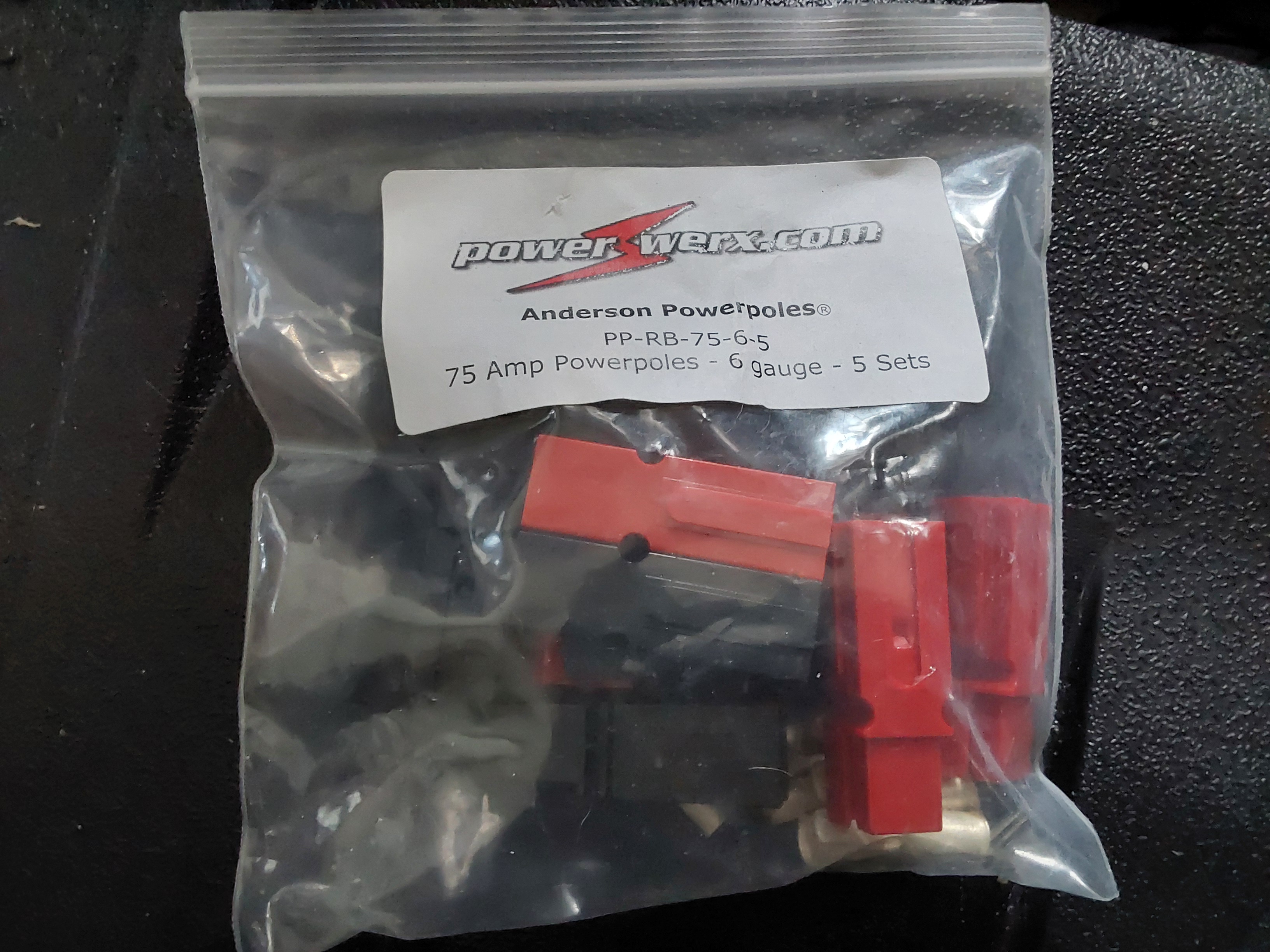
Probably this will only be for this one circuit though.  The wiring for the BMS is already robust, overkill for 30 or 50 amps.  If/when I do a 50 amp circuit, it will probably be to an Anderson connector rated to something over 50 amps.  Off the top of my head, I don't know the standardized size for Anderson connectors past 45 (the typical small standard).  I guess one way around this might---*might* be to use not one but two Anderson connectors.  10 gauge wiring running to a pair of Anderson connectors which then connect to my 50 amp load?  Maybe?  A dedicated path would be better, but I would nave the cutouts already in place.


Eric
 
John Weiland
pollinator
Posts: 2913
Location: RRV of da Nort, USA
896
  • Likes 4
  • Mark post as helpful
  • send pies
    Number of slices to send:
    Optional 'thank-you' note:
  • Quote
  • Report post to moderator

Allen Jackson wrote:.........change your primary wires to handle that higher current, or the wires may become the fuse in the system, with less than happy results.


Is there a chart or reference somewhere that shows wire gauge tolerance of intermittent/temporary amperage load versus sustained/continuous load?  Most battery jumper cables that I see seem to be ~2-4 AWG copper stranded wire....and these can handle 200 up to 1000 amps, but is this only temporarily?  In other words would those jumper cables be able to tolerate delivering 200+ amps for hours? As noted throughout thread, many applications will require longer periods of amperage draw, but it's not clear to me how wire size is calculated for intermittent vs. sustained draw.  Thansk!...

 
John Weiland
pollinator
Posts: 2913
Location: RRV of da Nort, USA
896
  • Likes 4
  • Mark post as helpful
  • send pies
    Number of slices to send:
    Optional 'thank-you' note:
  • Quote
  • Report post to moderator
A first test working pretty well so far.  I'm just powering some LED worklights with the new battery and a 700W pure sine wave inverter.  With the amp draw at ~3.2 A and some cycling on/off of the cell balancer, all is operating smoothly and quietly.  Hope to test more loads soon!....
InverterTest.jpg
[Thumbnail for InverterTest.jpg]
1stTestLEDlights.jpg
[Thumbnail for 1stTestLEDlights.jpg]
 
Allen Jackson
Posts: 137
26
  • Likes 2
  • Mark post as helpful
  • send pies
    Number of slices to send:
    Optional 'thank-you' note:
  • Quote
  • Report post to moderator

John Weiland wrote:

Allen Jackson wrote:.........change your primary wires to handle that higher current, or the wires may become the fuse in the system, with less than happy results.


Is there a chart or reference somewhere that shows wire gauge tolerance of intermittent/temporary amperage load versus sustained/continuous load?  Most battery jumper cables that I see seem to be ~2-4 AWG copper stranded wire....and these can handle 200 up to 1000 amps, but is this only temporarily?  In other words would those jumper cables be able to tolerate delivering 200+ amps for hours? As noted throughout thread, many applications will require longer periods of amperage draw, but it's not clear to me how wire size is calculated for intermittent vs. sustained draw.  Thansk!...


What you're referring to, is the "ampacity" of wire, and the allowable current through wire is dependent on multiple factors. The primary one is the temperature rating of the insulation. The most commonly available charts show the commonly used wire types with the most commonly found insulation types. Another factor is how many conductors are in the same area because mutual heating will derate the allowable values. Typical wire off-the-shelf, will have at least a 75 degree C rating, though some may be 90 C. Wire used in specialty applications will often have 105 C rated insulation, which will permit even higher current.

Welding cables and battery cables are often made with higher temp insulation for this reason. There are complex formulae for calculating the allowable values, published in the National Electric Code book, but most folks (including me) just find a table for the specific wire in question. Your wire should have a temperature rating printed on it, along with the wire size.

Here's a link to a chart with common wire options:  https://www.elliottelectric.com/StaticPages/ElectricalReferences/ElectricalTables/Allowable_Ampacities.aspx

And here's a chart with some of the higher temperature rated wire options:  https://www.remingtonindustries.com/content/Remington%20Copper%20Hook-Up%20Wire%20Ampacity%20Charts.pdf

Standard building wire (THHN) 2 AWG would be rated to carry 115 amps continuously, but this 2 AWG battery cable is suitable for the 215 amps continuously. The short-term value is going to be whatever you can push through the wire before the insulation either melts, burns, or the conductor melts/burns... (there are probably formulas for that too, but if you are pushing it that far, you can do the differential equations to solve for your limits!

Hopefully that clears up any confusion.
20260429_123931.jpg
[Thumbnail for 20260429_123931.jpg]
1000011278.jpg
[Thumbnail for 1000011278.jpg]
2 AWG battery cable with 105 C insulation
 
master pollinator
Posts: 2152
Location: Ashhurst New Zealand (Cfb - oceanic temperate)
746
duck forest garden fungi trees chicken cooking solar sheep wood heat woodworking rocket stoves
  • Likes 4
  • Mark post as helpful
  • send pies
    Number of slices to send:
    Optional 'thank-you' note:
  • Quote
  • Report post to moderator
Keep in mind that the temperature ratings of the different classes of wire will change if they're run through conduit, or underground, versus in free air or a cavity (plenum), and as Allen pointed out, a single cable dissipates heat more efficiently than two, three, or four in a bundle. The tables should guide you on this.
 
Allen Jackson
Posts: 137
26
  • Likes 4
  • Mark post as helpful
  • send pies
    Number of slices to send:
    Optional 'thank-you' note:
  • Quote
  • Report post to moderator
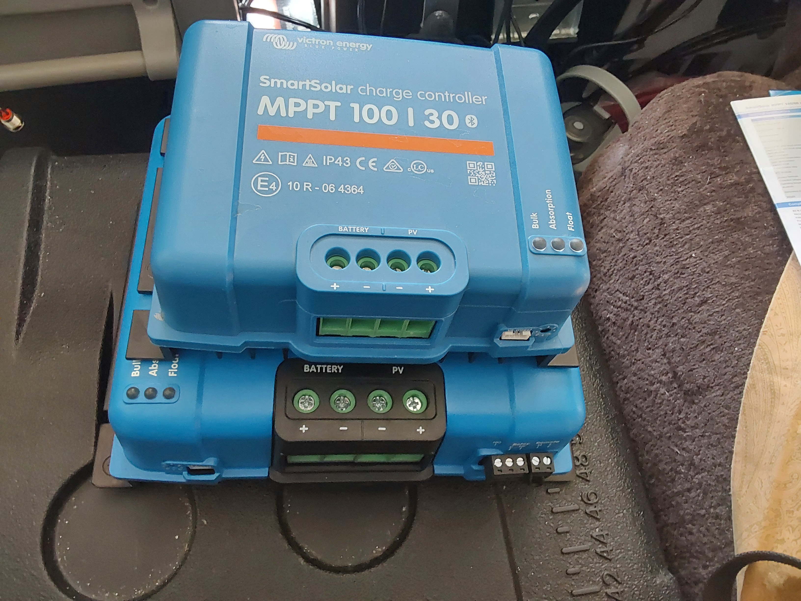
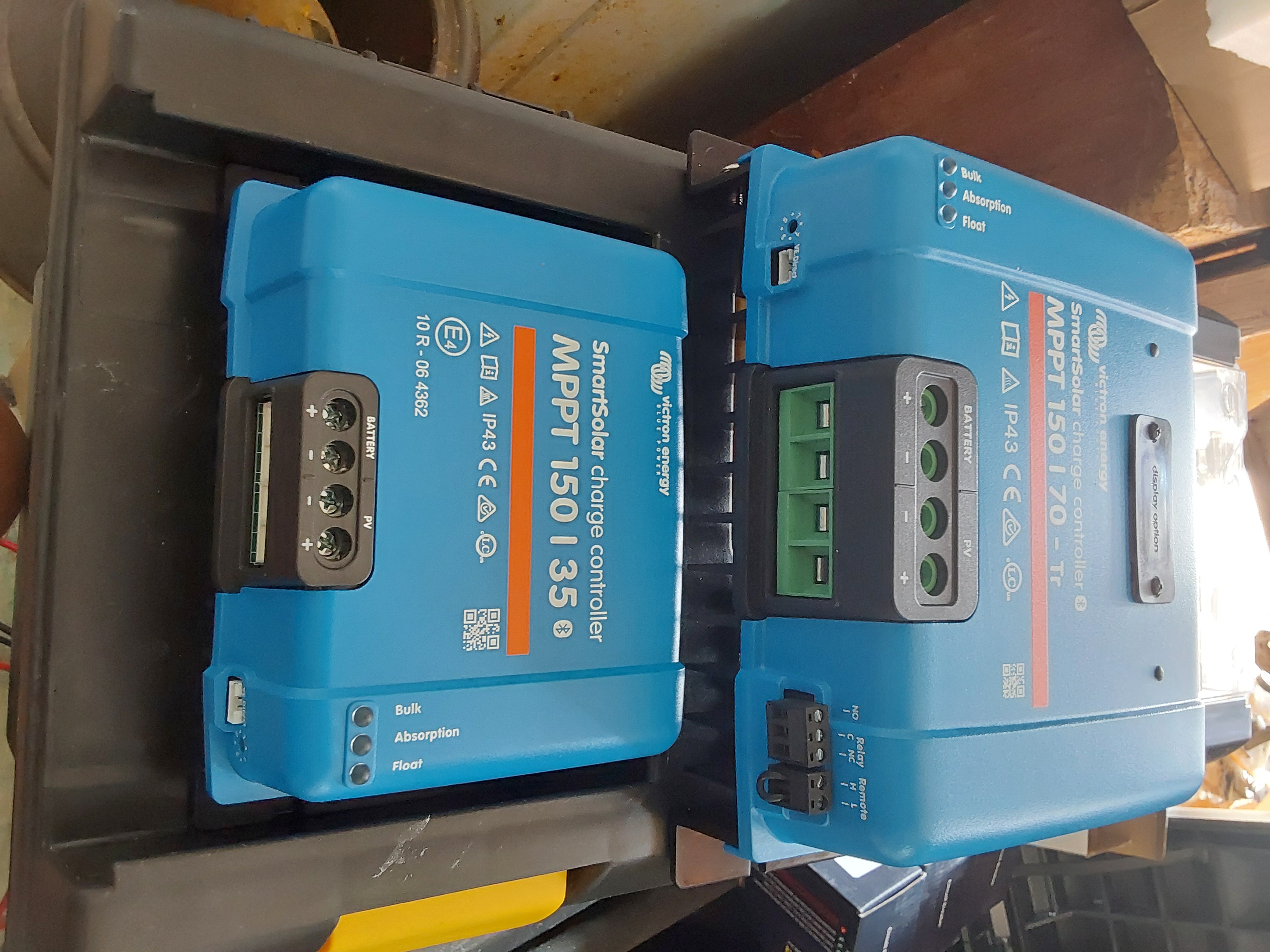
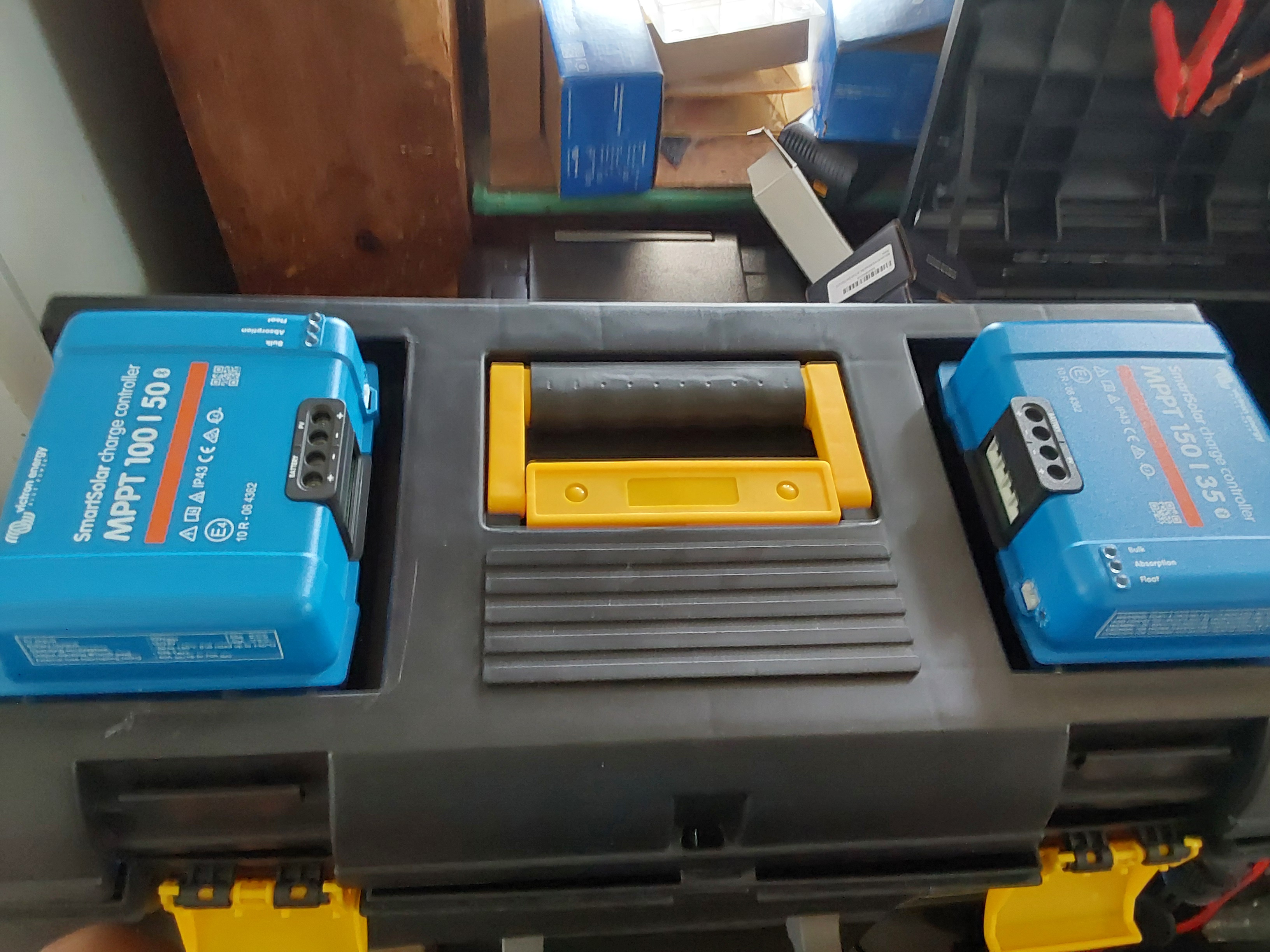
I guess I was a bit naive when I was shopping for charge controllers, & I mistakenly assumed because they all looked the same, that they were the same size, and I could swap them interchangeably...

I was (really) wrong about that!  The 30 amp controller is a loose fit in the toolbox lid slot. The 35 amp controller is a press fit into the same slot, and the 70 amp controller I got today, well, it's a big brother to both of them, & won't exactly fit on the end of the toolbox...

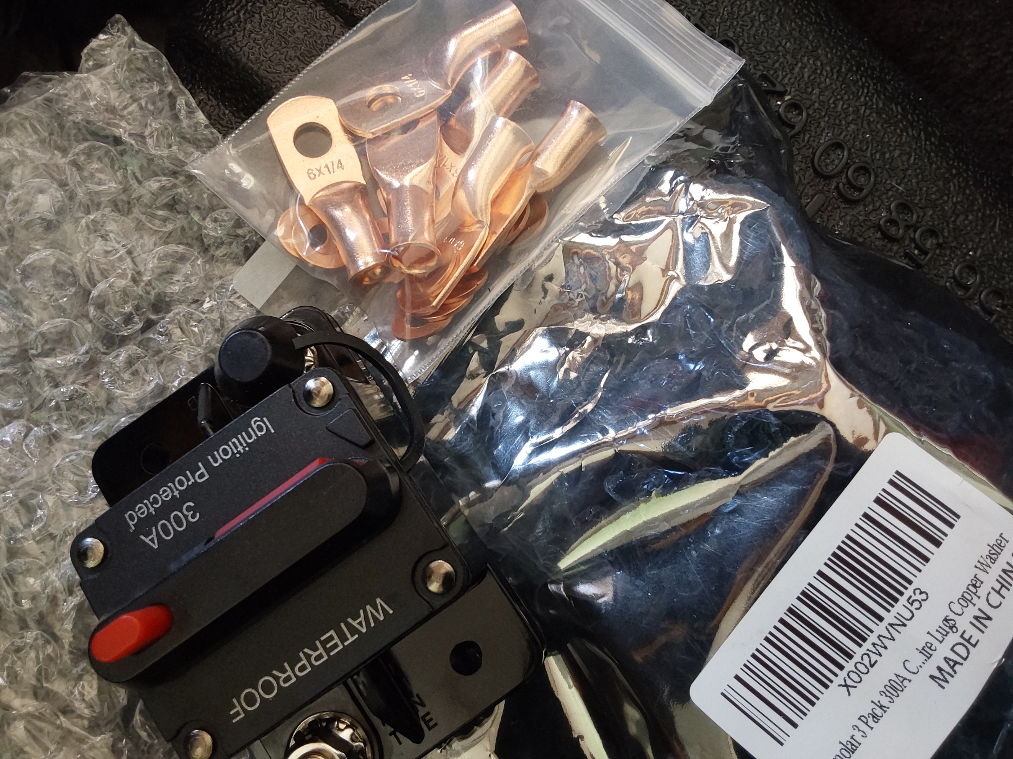
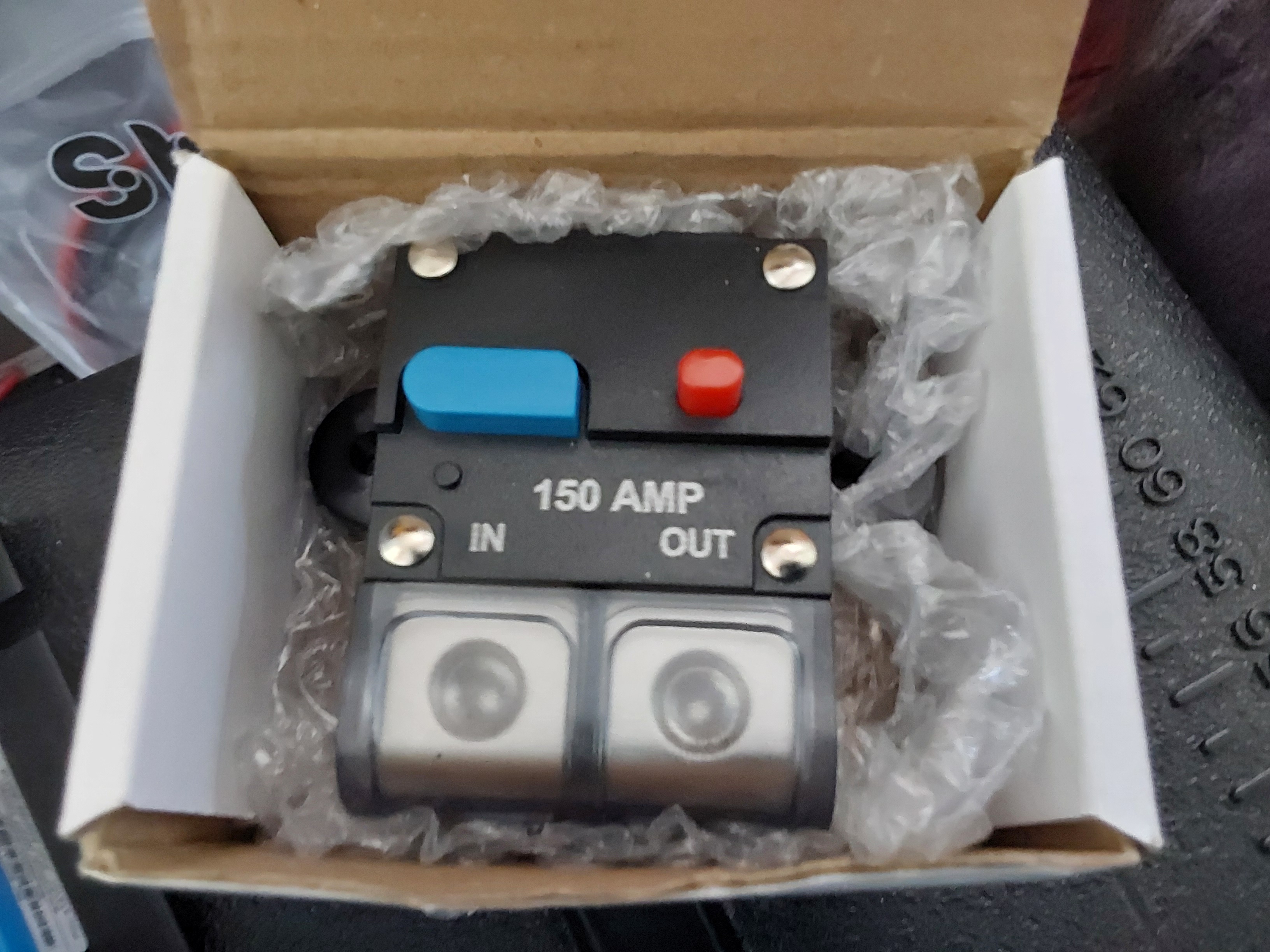
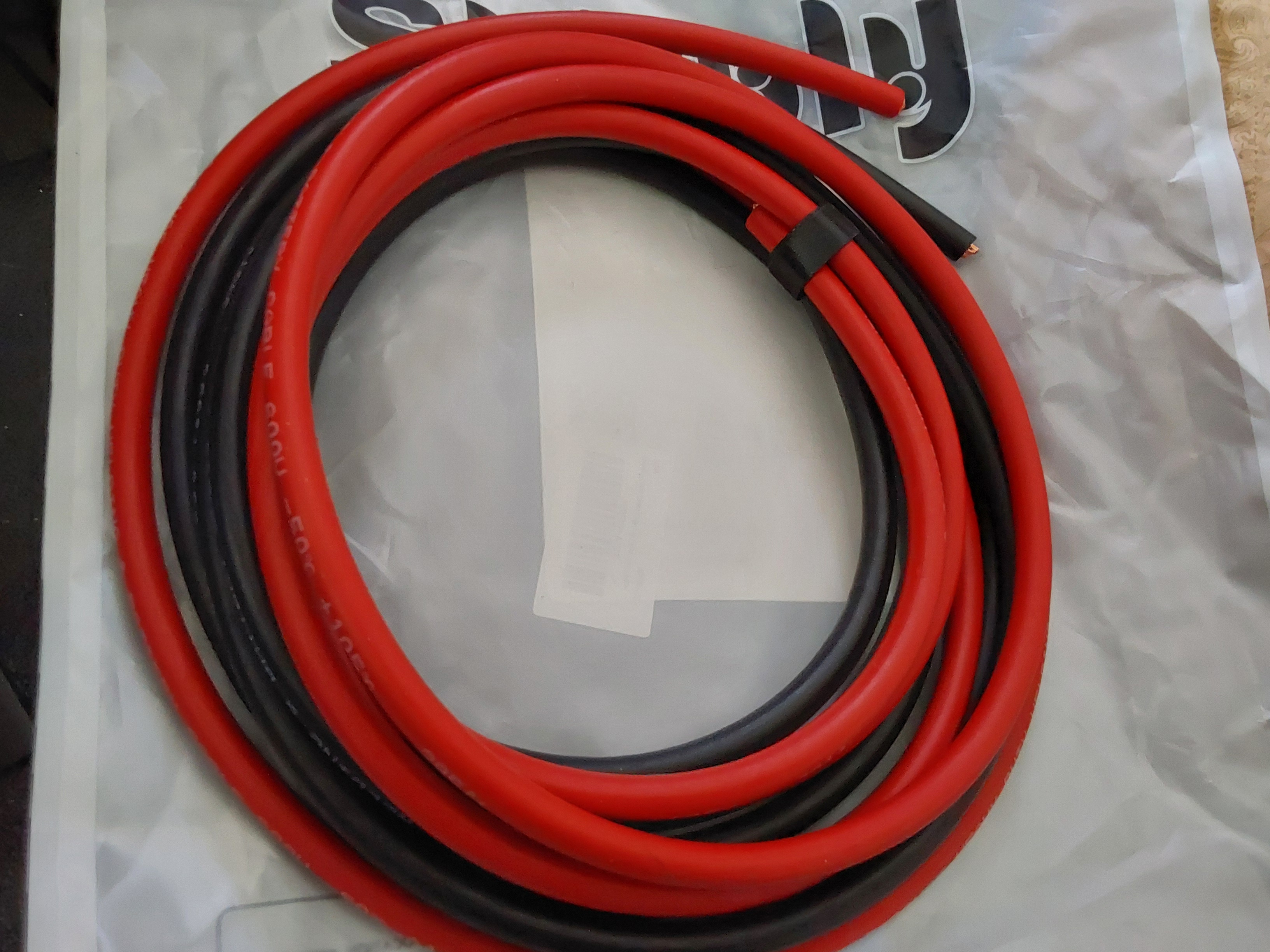
I was also re-doing the wiring today and got some surprises there too. I previously had not installed all the circuit protection that was appropriate for everything, just connecting for testing (temporarily). The "300 amp" breakers I'd bought (certainly cheap Chinese products) came with 6 AWG copper lugs, and I don't know in which universe, one can safely use 6 AWG wire to carry 300 amps... I have the correct size terminal lugs for that, but I have to wonder about their other customers who take the package as gospel...

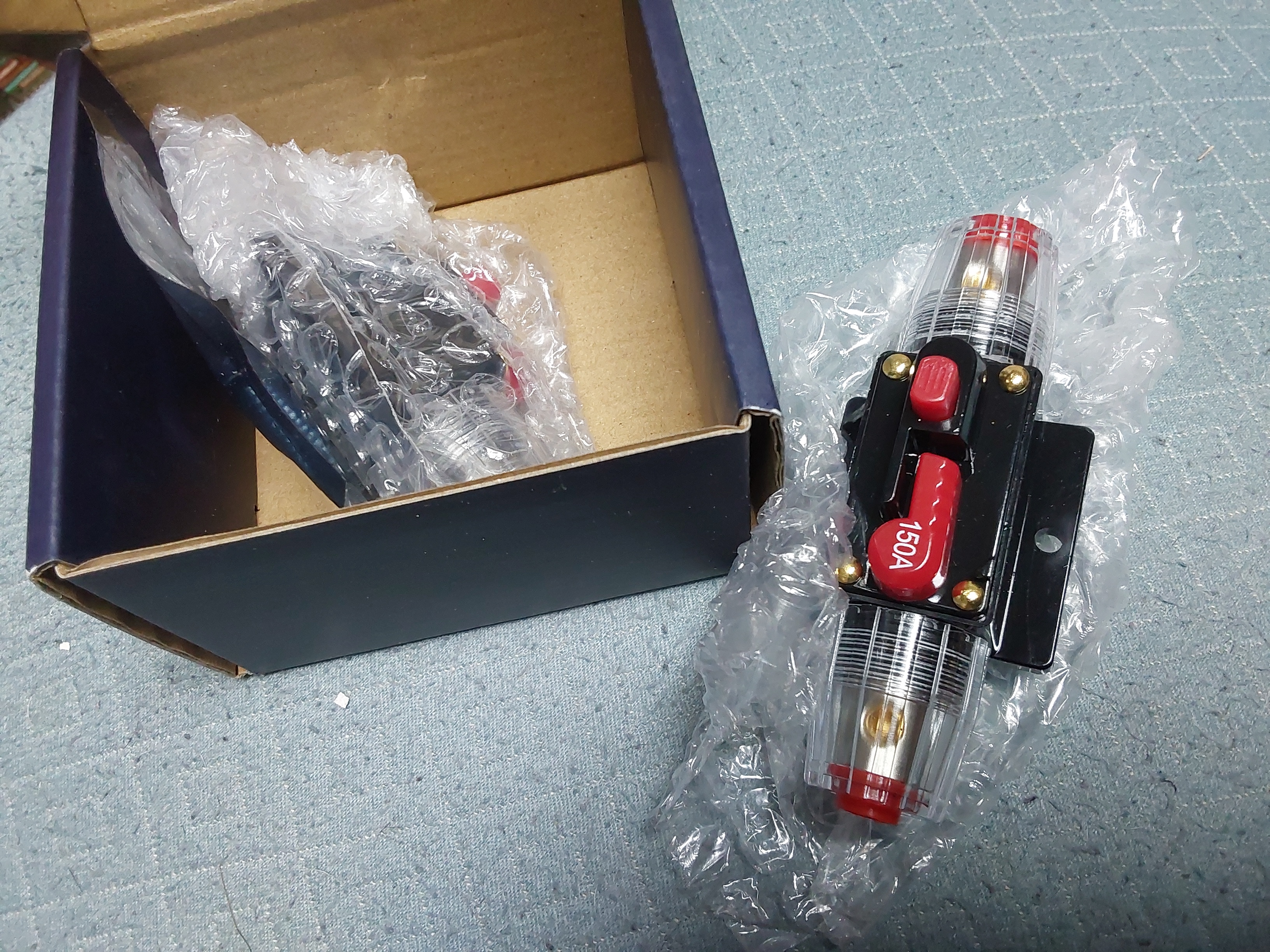
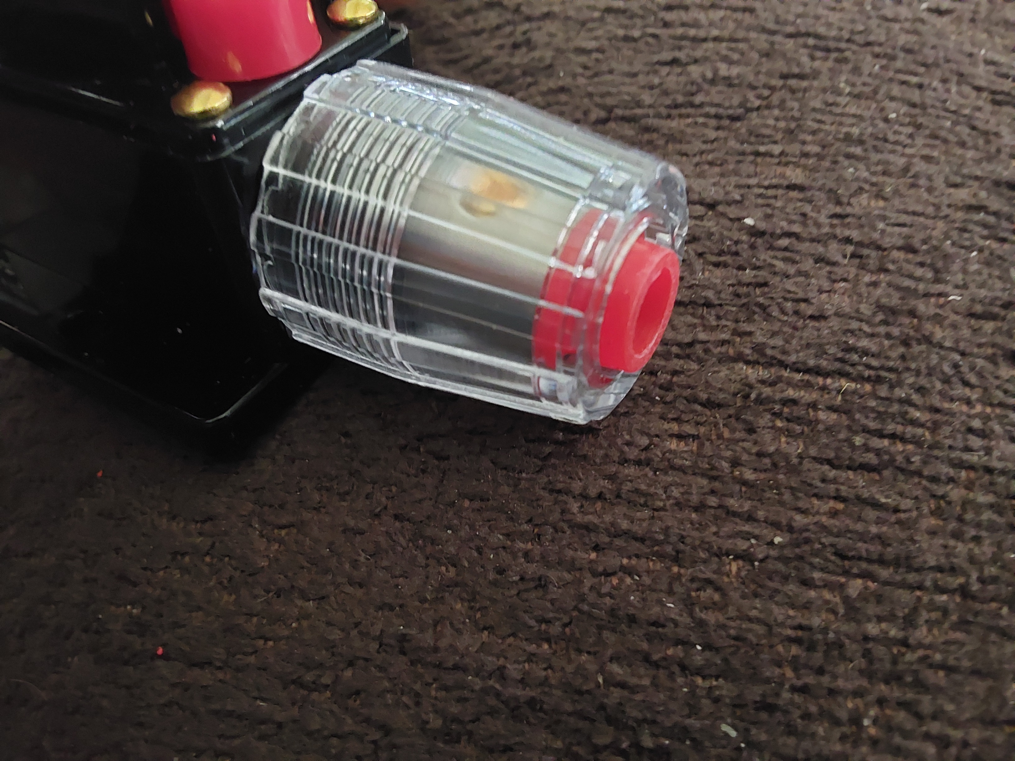
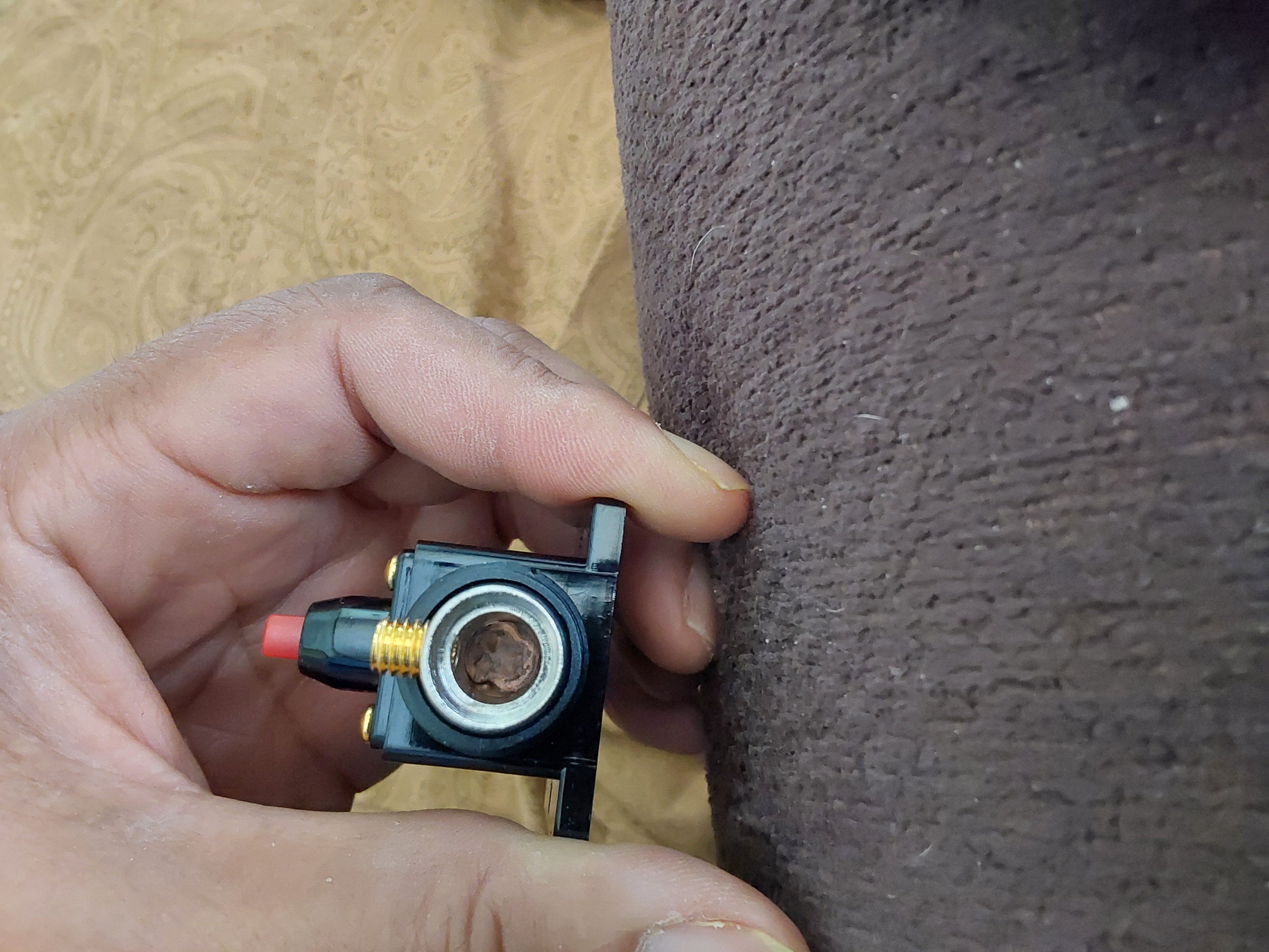
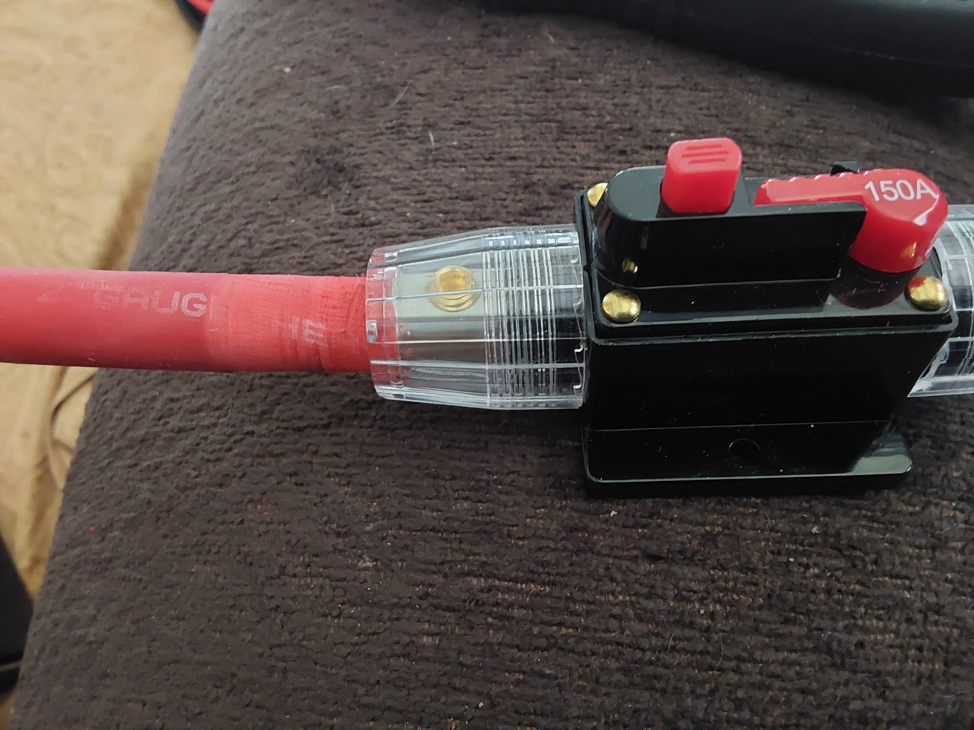
In any case, I don't want to use a 300 amp circuit protector there, I only want a 150-175 amp protector on the battery, because the wire I'm using is only rated for 215 amps, and I shouldn't need any more than 150 amp when things are going well. Next problem - my 150 amp breakers are an inline type that's only listed to work with 3-15 AWG wire (if one is using 8-15 AWG on a 150 amp circuit, the breaker is just there for show, before the fire, and even 4-6 AWG is more of a slow-blow/burn fuse that will go before the breaker does... ) , and I am using 2 AWG. You may have seen these type of breakers on Amazon too (more cheap Chinese products), and I've found with a lot of work, it's possible to force 2 AWG welding wire into the terminal. The wire part is not bad, but the insulation is a real forced fit! Unfortunately I don't have any of the other kind, with the M6 terminals.

I have to pause for more reflection on how best to "skin this polecat".

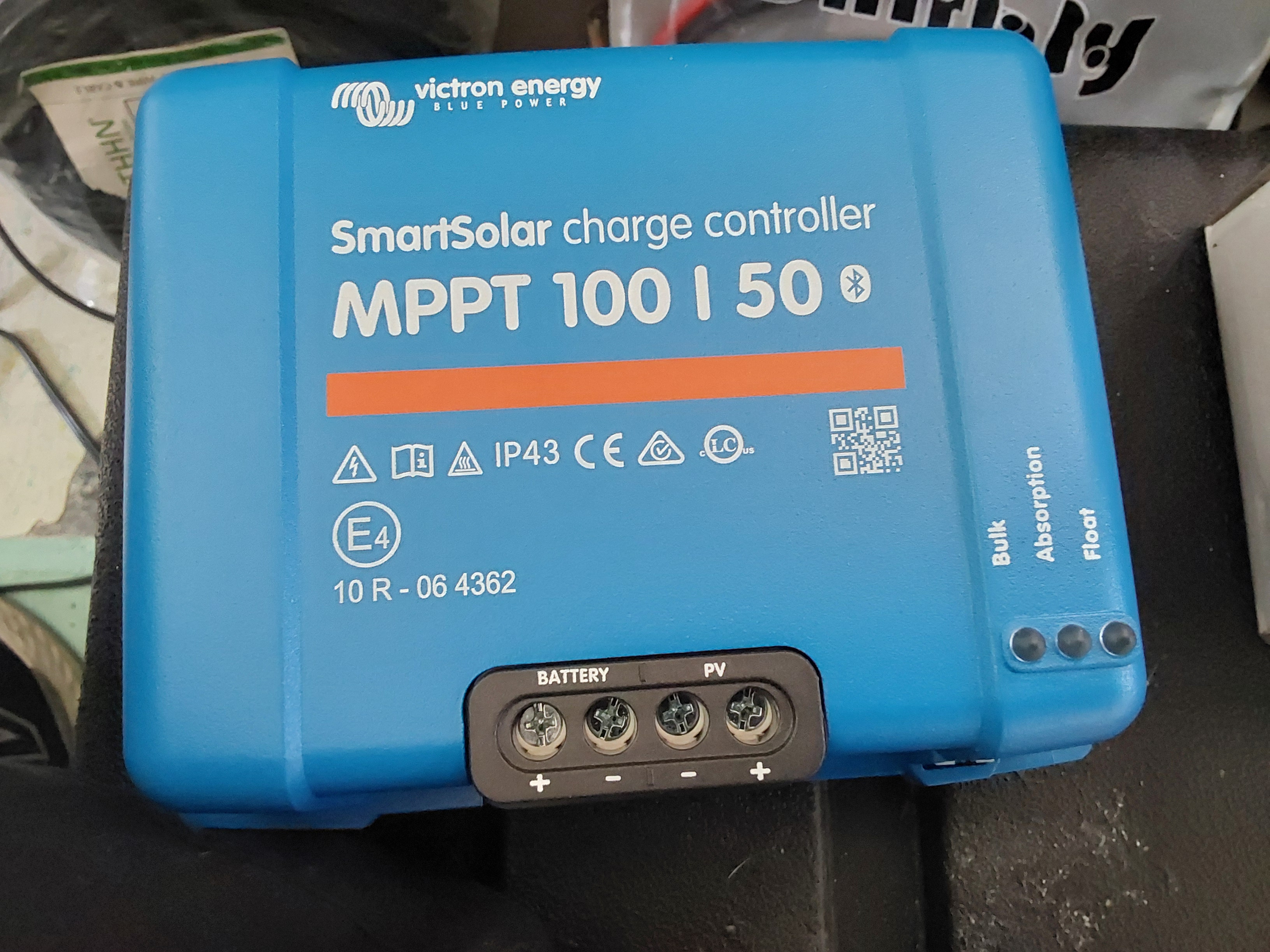
Update:  I've now discovered that the best choice for a solar controller (for this specific project), is likely to be the Victron MPPT 100 | 50 model. I have the 100 | 30 model, which tops out just over 400 watts, but the 50 amp variant, which can handle just over 700 watts and it's less than $200 (and it's the same physical size as the 30 amp version).

The 150 | 70 model is substantially larger, tops out at nearly 1000 watts, costs over $330, and probably a bit of overkill (for this project, or I'll now need to get more solar?).
20260513_165024.jpg
The 100/30 controller on top of the 150/70 one...
20260513_165740.jpg
The 150/35 is a press fit in the slot, but the 150/70 isn't even close
1000011466.jpg
This size terminal lug shouldn't be paired with this size breaker! Ever!
1000011084.jpg
Supposedly this is a 150 amp breaker, even though the wire size is rather limiting
1000011477.jpg
To put in 2 AWG wire, remove the weather seal (no need or room for it anyway)
1000011472.jpg
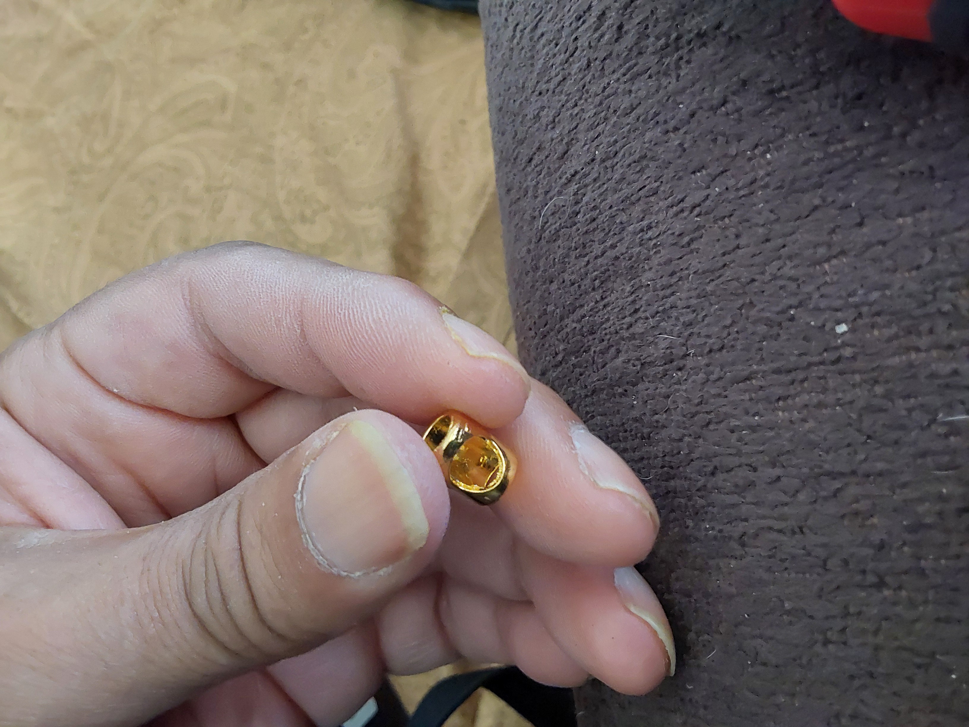
Remove the gold (plated?) ferrule too, no room for that, & the set screw doesn't need it
1000011471.jpg
Back the set screw out or remove it.
1000011467.jpg
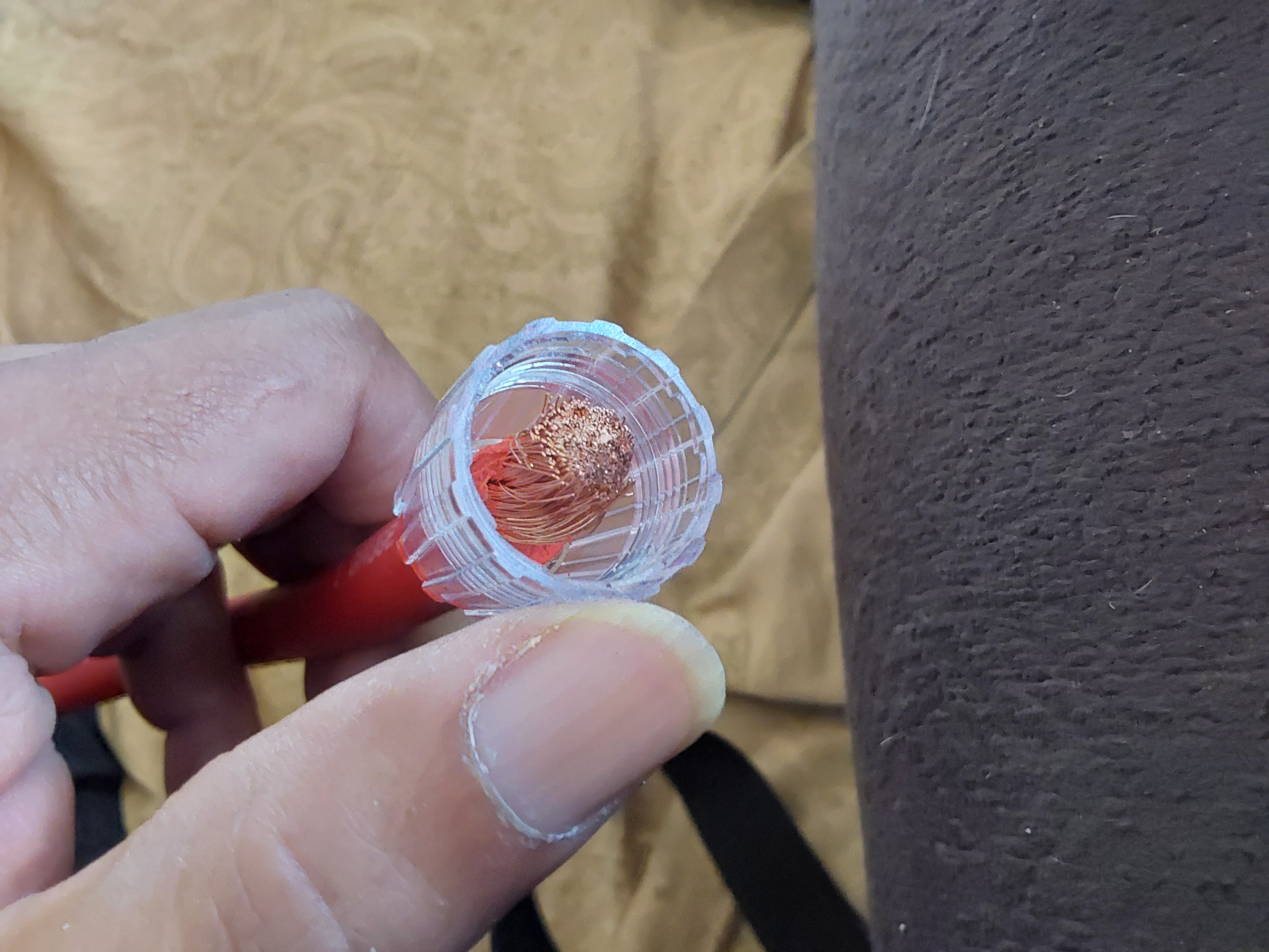
Twisting and pushing the cover on, it is possible but slow going
1000011468.jpg
It would be easier to sand down the insulation or shave it slightly before installing the cover
1000011469.jpg
It would also be a little easier to get the cover on prior to cutting the insulation, in terms of keeping the wire bundle from fraying
1000011474.jpg
You have to push it back far enough to get to the set screw
1000011475.jpg
But it is possible, don't give up!
1000011476.jpg
Not quite as hard to move the cover back into position, & it gets easier once you get the threads to engage
 
Allen Jackson
Posts: 137
26
  • Likes 4
  • Mark post as helpful
  • send pies
    Number of slices to send:
    Optional 'thank-you' note:
  • Quote
  • Report post to moderator

Eric Hanson wrote:Absolutely I will change the wiring.  

Probably this will only be for this one circuit though.  The wiring for the BMS is already robust, overkill for 30 or 50 amps.  If/when I do a 50 amp circuit, it will probably be to an Anderson connector rated to something over 50 amps.  Off the top of my head, I don't know the standardized size for Anderson connectors past 45 (the typical small standard).  I guess one way around this might---*might* be to use not one but two Anderson connectors.  10 gauge wiring running to a pair of Anderson connectors which then connect to my 50 amp load?  Maybe?  A dedicated path would be better, but I would nave the cutouts already in place.
Eric


The Anderson PowerPole connectors are available in 75 amp, 120 amp, and 180 amp sizes, but if you want a convenient way to connect a pair of wires, the Anderson "SB" series is probably a better fit. The actual current rating is limited by the wire used, the actual voltage ratings of all of them is 600 Vdc, and the colors and sizes are more to key connections for safety - - the SB50 & SB75 use the exact same terminal contacts, and the shells are the same physical size, but you can't plug them into each other.

Edit:  Apparently the ones I have from 20+ years ago are SB50s. SB50s with 6 AWG wire is current limited by the 6 AWG wire, not the "SB50s" designation. They do use the same terminals as the PowerPole 75 connectors use.

Please check your 10 AWG wire insulation before you try to run 50 amps through it, for the common wire types, one would typically be using 8 or 6 AWG for a 50 amp circuit.

Trivia - The "SB" part of the Anderson connector stands for storage battery...
20260513_182826.jpg
Anderson PowerPole 75 connectors
 
John Weiland
pollinator
Posts: 2913
Location: RRV of da Nort, USA
896
  • Likes 5
  • Mark post as helpful
  • send pies
    Number of slices to send:
    Optional 'thank-you' note:
  • Quote
  • Report post to moderator
If the following has already been addressed, please provide a link and I will remove this current entry.

Battery vs. cell balancing---

I'm going on what I've read and may be missing something with my argumentation, but hopefully clearing up a confusion for me.  LiFePO4 batteries like to have evenly matched cells and increasingly include active or passive circuitry to achieve this.  For most of the past few years that I've been researching LiFePO4 batteries leading up to the build in this thread, the mantra has been to buy the battery voltage in a size ready to use for your application:  If you will need 48V, then buy a 48V battery instead of series-connecting 4 X 12V batteries to get there.  The rationale given was that batteries within a series string could go out of balance with each other and cause myriad problems with charging, discharging, and ultimately battery health.

Increasingly, I'm seeing reports of external balancers being sold to perform the job *between* batteries at the string level that an active or passive balancer does to cells *within* a single battery.  So my question is whether or not there is some reason that this approach of balancing between *batteries* connected in series is being dismissed where as the same activity being applied to *cells* within the same battery is so well accepted and achieved.  Is it just that the system as a whole is being asked to do too much and there is increased danger to the battery and/or cell health if this is done?  Although connecting all of those batteries together can be laborious and reduce the compactness of the system, the flexibility of having multiple 12V batteries and in which array they are being used at any given time seems advantageous as well.  Thoughts?  Thanks!....
 
Allen Jackson
Posts: 137
26
  • Likes 5
  • Mark post as helpful
  • send pies
    Number of slices to send:
    Optional 'thank-you' note:
  • Quote
  • Report post to moderator

John Weiland wrote:If the following has already been addressed, please provide a link and I will remove this current entry.

Battery vs. cell balancing---

I'm going on what I've read and may be missing something with my argumentation, but hopefully clearing up a confusion for me.  LiFePO4 batteries like to have evenly matched cells and increasingly include active or passive circuitry to achieve this.  For most of the past few years that I've been researching LiFePO4 batteries leading up to the build in this thread, the mantra has been to buy the battery voltage in a size ready to use for your application:  If you will need 48V, then buy a 48V battery instead of series-connecting 4 X 12V batteries to get there.  The rationale given was that batteries within a series string could go out of balance with each other and cause myriad problems with charging, discharging, and ultimately battery health.

Increasingly, I'm seeing reports of external balancers being sold to perform the job *between* batteries at the string level that an active or passive balancer does to cells *within* a single battery.  So my question is whether or not there is some reason that this approach of balancing between *batteries* connected in series is being dismissed where as the same activity being applied to *cells* within the same battery is so well accepted and achieved.  Is it just that the system as a whole is being asked to do too much and there is increased danger to the battery and/or cell health if this is done?  Although connecting all of those batteries together can be laborious and reduce the compactness of the system, the flexibility of having multiple 12V batteries and in which array they are being used at any given time seems advantageous as well.  Thoughts?  Thanks!....


I suspect that it's a case of "too many cooks"...

Each battery (bank of cells) should must have its own BMS to protect & increasingly to also balance those cells. Auxiliary balancers gained popularity because some BMSs either didn't have balancing functionality or it was so anemic as to be ineffective. My 40 amp BMS only had a 400 mA balancer, which wasn't able to effectively balance the 314 Ah battery I'd connected it to.

It's possible to have different batteries (banks of cells) wired in parallel, which actually should work perfectly fine once they're connected to each other, since each BMS should cut out their batteries as the limits have been reached, & even external balancers are still limited to only 1 bank of cells (it's possible to have multiple balancers per bank, but they don't cross banks).

When you have multiple batteries in parallel, they'll automatically "balance" to the same voltage, and in the process, one or more may deplete a bit to charge up the lower voltage batteries in the group. No external hardware is needed except the bus bars connecting them.

It's going to cause a major spark when they're first connected, if they're not exactly the same voltage, which is why it's not uncommon (if the spark/arcing is not desirable), to first connect them with a load between them, like an incandescent light bulb, and when the light bulb goes out, the voltage has fallen to very low or 0...  An automotive halogen bulb will work well enough and probably is easier to get than any "external balancer" you can find. (Once the light goes out, the light can be shorted with the appropriate heavy duty switch that's rated for the current).

Alternatively, one can charge each bank to the exact same voltage and connect them before they have a chance to drift. Once connected, they can be safely used, charged, and discharged as a group.

This is also where the big Anderson SB connectors shine - they can handle both high current, but also a decent amount of arcing when connected under a load.

One of the redeeming features of lithium battery chargers (including solar charge controllers), is that they monitor the charging current, and stop charging once the charging current falls below the "charged" threshold. They don't need to have intelligent communication with the battery or batteries in question, as they'll supply current when the "suckling children" are hungry enough to eat, but stop once the demand drops off to barely anything (I think my 20 amp charger stops below 2 amps?).

Because of this, no matter how many batteries are connected, as long as any of them are still actively charging, the charger will supply power, and the charger will remain off, even if it is still connected, until the voltage drops below the preset level for recovery/recharging. Most BMS will also have a recovery voltage that the system will have to drop below, before it will re-enable charging.
 
John Weiland
pollinator
Posts: 2913
Location: RRV of da Nort, USA
896
  • Likes 6
  • Mark post as helpful
  • send pies
    Number of slices to send:
    Optional 'thank-you' note:
  • Quote
  • Report post to moderator
Thanks, Allen....this helps with my conceptualization of inner workings of these beasties....  One approaching priority will be garden irrigation pumping, preferably 24 - 48VDC with some solar charging involved.  Here again I'm weighing the multiplexing of 12V batteries to get the power required for the pump or just purchase some 24V or 48V pre-fabs.  Decisions, decisions.....

A few extra photos to go with the 12V build....so far all going quite well.  I was able to add the on/off button for the BMS to the side of the case (second photo) and decided to test out also the quick-release cable ends that work with standard battery posts.  I removed the M8 bolts that were evident in the photo in the previous entry(s) and had been used to fasten the ring-terminals of the inverter cables to the battery.  As I've observed before, it's common for the ring-terminal diameter to be small enough to slide into the quick-release wire clamp and held in place by the clamp screws.  Then the quick release units themselves were clamped on to the battery posts.  Everything fired up fine, yet I wanted to test a larger load this time.  So I plugged in a vacuum cleaner (120V/4A) and hit the power switch.  I was surprised to see that the math added up:  The BMS app was showing a ~40A draw....which from a 12V battery would be necessary for providing 120V@4A to the sassy Oreck vacuum.  The surge on start-up was about 50A briefly, but settled in quickly.  Pleased so far!....
ConnectorCloseup.jpg
[Thumbnail for ConnectorCloseup.jpg]
QuickiesOnPosts.jpg
[Thumbnail for QuickiesOnPosts.jpg]
OreckSucksAmps.jpg
[Thumbnail for OreckSucksAmps.jpg]
 
Allen Jackson
Posts: 137
26
  • Likes 5
  • Mark post as helpful
  • send pies
    Number of slices to send:
    Optional 'thank-you' note:
  • Quote
  • Report post to moderator
BTW, Eric & anyone else who is looking for portability with solar panels, the Predator 200 watt panels are only 24 Vdc panels, so they can't be used to charge a 24 Vdc battery unless you use at least 2 of them in series, because the charge controller will need to have a higher supply voltage than the output/charging voltage, and a "24 Vdc" LiFePO4 battery will need 28.4 Vdc to charge it (lower than the single panel output of the Predators).

Powerwerx sells a 36 Vdc 300 watt foldable panel that's close to the Predators in cost/watt, but you can start with 1 of them and add more as circumstances permit.  Folded up, they're 27.75" x 24.25" x? vs the Predators (25.25" x 21.25" x 2.25")

https://powerwerx.com/fsp-300w-folding-solar-panel

There are also numerous other options on Amazon for 300 watt folding solar panels, although you have to be careful about the listings - Amazon doesn't require vendors to be technically accurate on their listings and relies on the shopper feedback to police the vendor listings (but requires folks buy it and complain/return/review the products before they get any reputation for being good or bad...
(Some of the listings are way too good to be true, too)

Here's one that could be legit, but I'm sure it's a Chinese exporter, so the shipping times are likely a few weeks+:

https://www.amazon.com/LVYUAN-Portable-Efficiency-Adventures-Generator/dp/B0FQHGJMRK?

They're cheap enough that I'd consider them if I needed more panels, but not in a hurry.
 
John Weiland
pollinator
Posts: 2913
Location: RRV of da Nort, USA
896
  • Likes 5
  • Mark post as helpful
  • send pies
    Number of slices to send:
    Optional 'thank-you' note:
  • Quote
  • Report post to moderator

Allen Jackson wrote:.....the Predator 200 watt panels are only 24 Vdc panels, so they can't be used to charge a 24 Vdc battery unless you use at least 2 of them in series,...


Allen,  

This is another issue that I wonder about since I dove into solar with the charging of a golf cart and an electric 4X4....   I recall shopping around a lot for panel sizes that would deliver greater than 36V (for the golf cart) and 48V (for the 4X4). The panel found for the golf cart has an output of ~45-50V (327W) and so the controller was at ease with this combination. Then I fell down the rabbit hole of buck-boost controllers (MPPT being my choice) and decided to try one with the panel on my 4X4 Polaris Ranger.  I found a 380W panel whose voltage was in the 30-40V output range and tried that with a boost-capable controller and it seems to be working well so far.  That is, it is charging the 48V bank on the Ranger, even if it has to sacrifice some amps to do so.  Are there any ways to estimate when such a scheme will not work?.....How low below the battery voltage can you go before even a boost controller can't charge a battery with too small of a PV panel?  Thanks....
 
Allen Jackson
Posts: 137
26
  • Likes 4
  • Mark post as helpful
  • send pies
    Number of slices to send:
    Optional 'thank-you' note:
  • Quote
  • Report post to moderator
That's going to be very heavily dependent on the charge controller. There's a lot of cheap junk controllers that even claim to be MPPT controllers, but require such a tight range of input and output voltages that you'd pull out your toenails before you were happy with the results. I tend to stay away from boost controllers, because the variable sunlight is already one strike against you with all controllers, so having a controller that's having to do DC-to-DC up conversion while also trying to optimize solar power from a varying source... And it's too easy to just double up the solar panels to get over the recommended minimum voltage.

A rule of thumb I use, is panel or rather charge controller input voltage should be at least 5 Vdc higher than the charge controller output voltage and more is better, up to the limit of the controller input maximum voltage minus a safety margin for cold weather voltage drift (solar panels increase voltage output as they get colder).

For example, the Predator 200 watt panel officially has an open circuit voltage (VOC in the specs) of 24.5 Vdc, but in operation, they ran about 21.x Vdc. My original solar controller is a Victron MPPT 100 | 30, which means it can handle up to 100 volts input, and outputs about 30 amps when charging. Since I was charging a "12 Vdc" LiFePO4 battery, it would need to charge at about 14.2 Vdc, but if it was connected to a "24 Vdc" battery, it will still produce only 30 amps, but at 28.4 Vdc, & the solar input will need to be at least about 33.5+volts before the controller will start producing any power output.

In theory, I could have connected 4 of the Predator 200 watt panels in series to it, which should produce an open circuit voltage of 98 Vdc (24.5 Vdc x 4), but in my opinion, that's too close to the maximum charge controller input voltage to chance burning it out (& I have "Y" connectors, so I can easily halve the voltage and double the current, running 2 parallel strings to get the same power with no risk). Even if in operation, the voltage would be down to only about 84 Vdc, if they were connected or disconnected without removing the light from the panels, there could be a voltage spike from the string that exceeded 100 volts, and then the controller is smoked... Better safe than sorry!

A few years ago, I attended a seminar to hear Mike Reynolds (the creator of the Earthship concept), and by that time the Earthship concept had been thru several generations of revisions, so he was described what he'd found out that worked and what things he'd found maybe worked, but not well enough to bother with because the economy of doing differently had changed enough to take a different path.

The first generation Earthships used solar panels on a movable mount, so they could be tilted and tracked to follow the sun, but over time the cost of solar panels fell & the maintenance of the trackers became a bigger problem than just increasing the number of solar panels to increase the solar energy collection... Solar panels are even cheaper now than they were then, and no one has ever been heard to say "I have too many solar panels...".
 
Allen Jackson
Posts: 137
26
  • Likes 5
  • Mark post as helpful
  • send pies
    Number of slices to send:
    Optional 'thank-you' note:
  • Quote
  • Report post to moderator
I've found a solution, at least for the size wire/insulation I am using for my primary wire vs the inline fuse with the too-small wire ports.

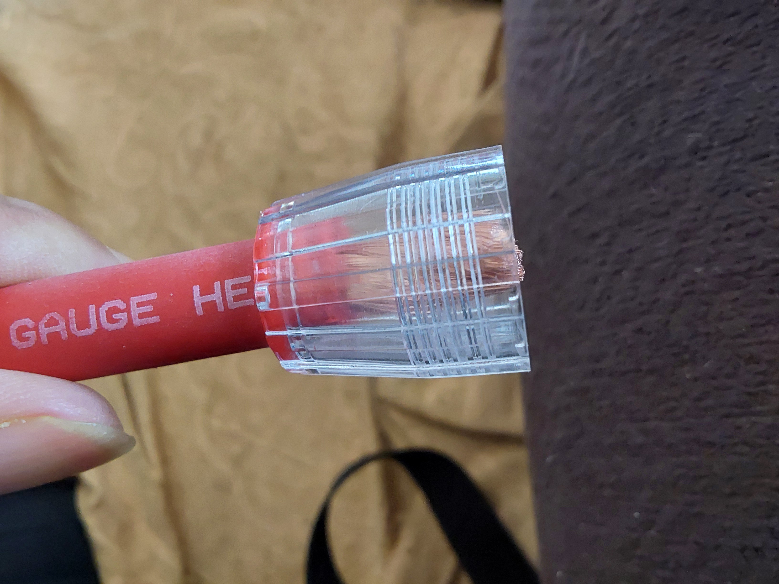
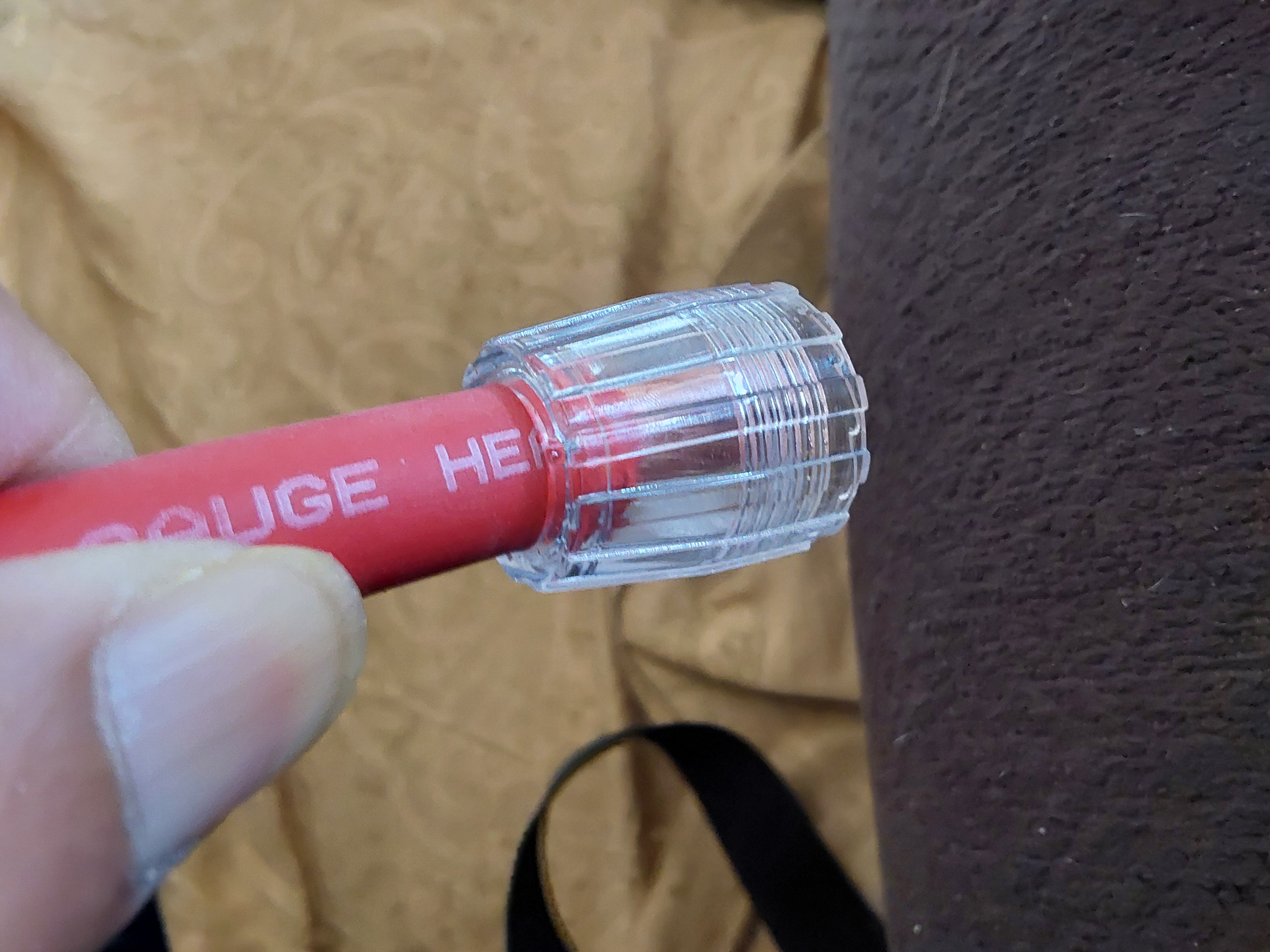
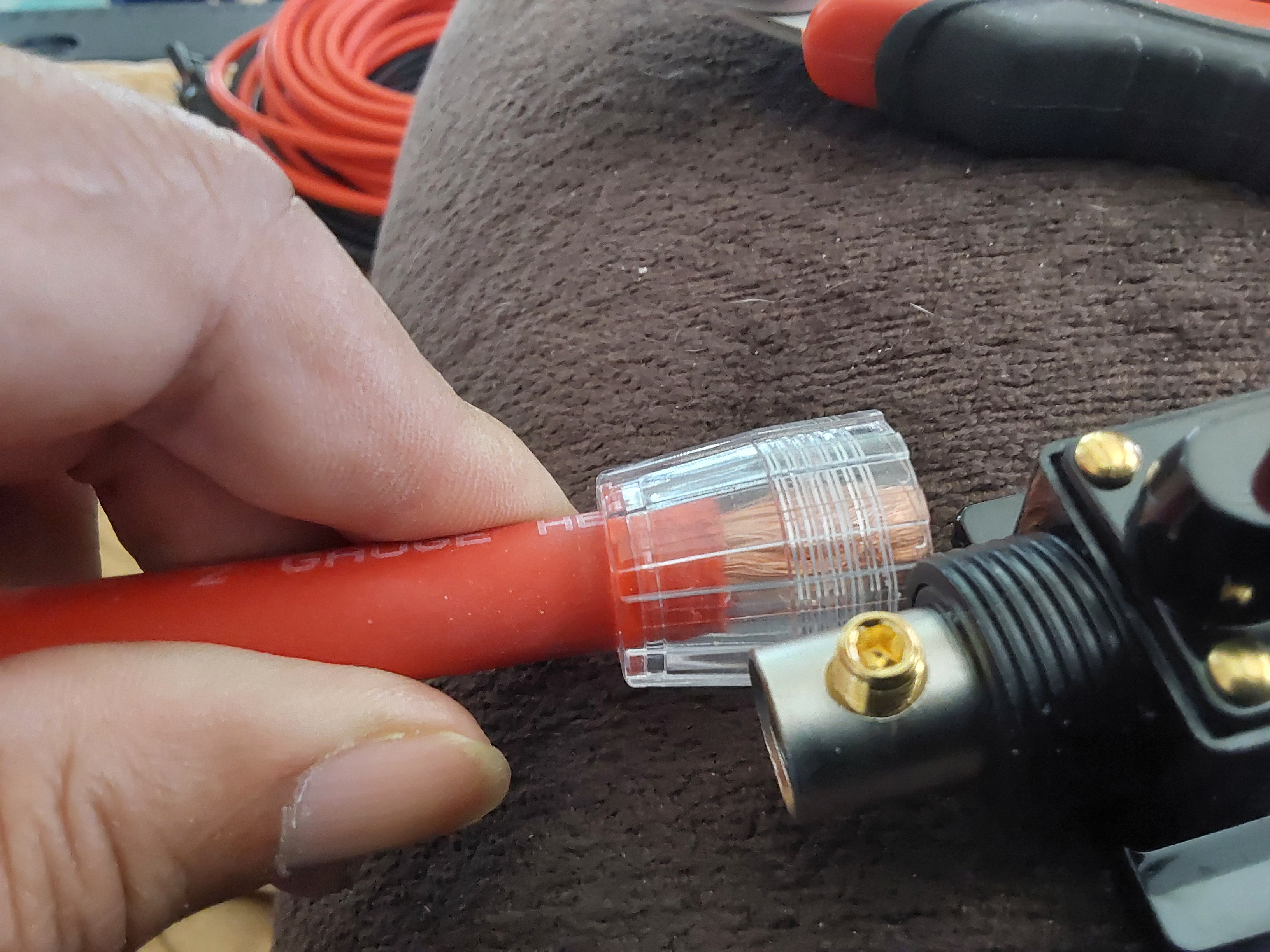
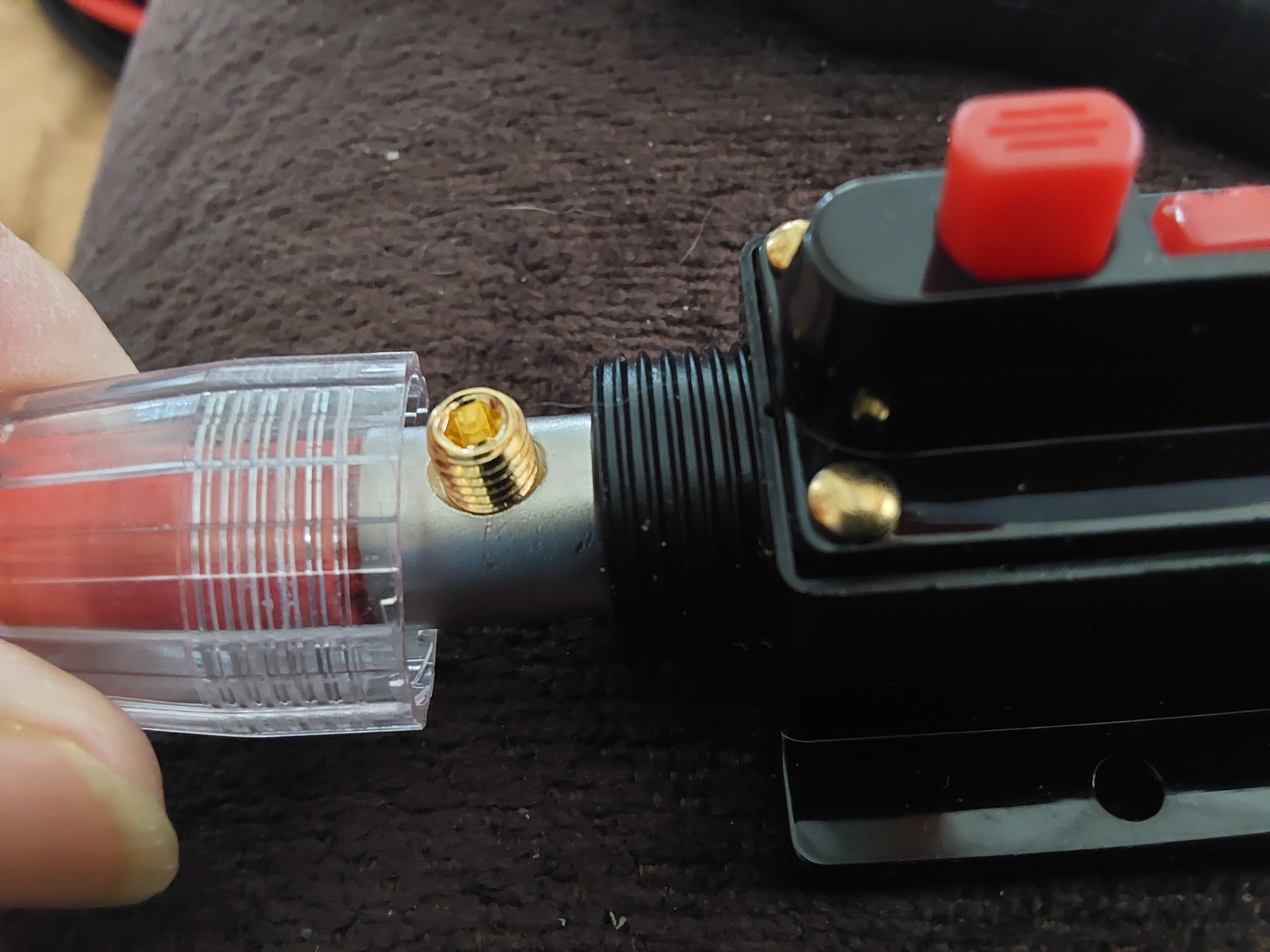
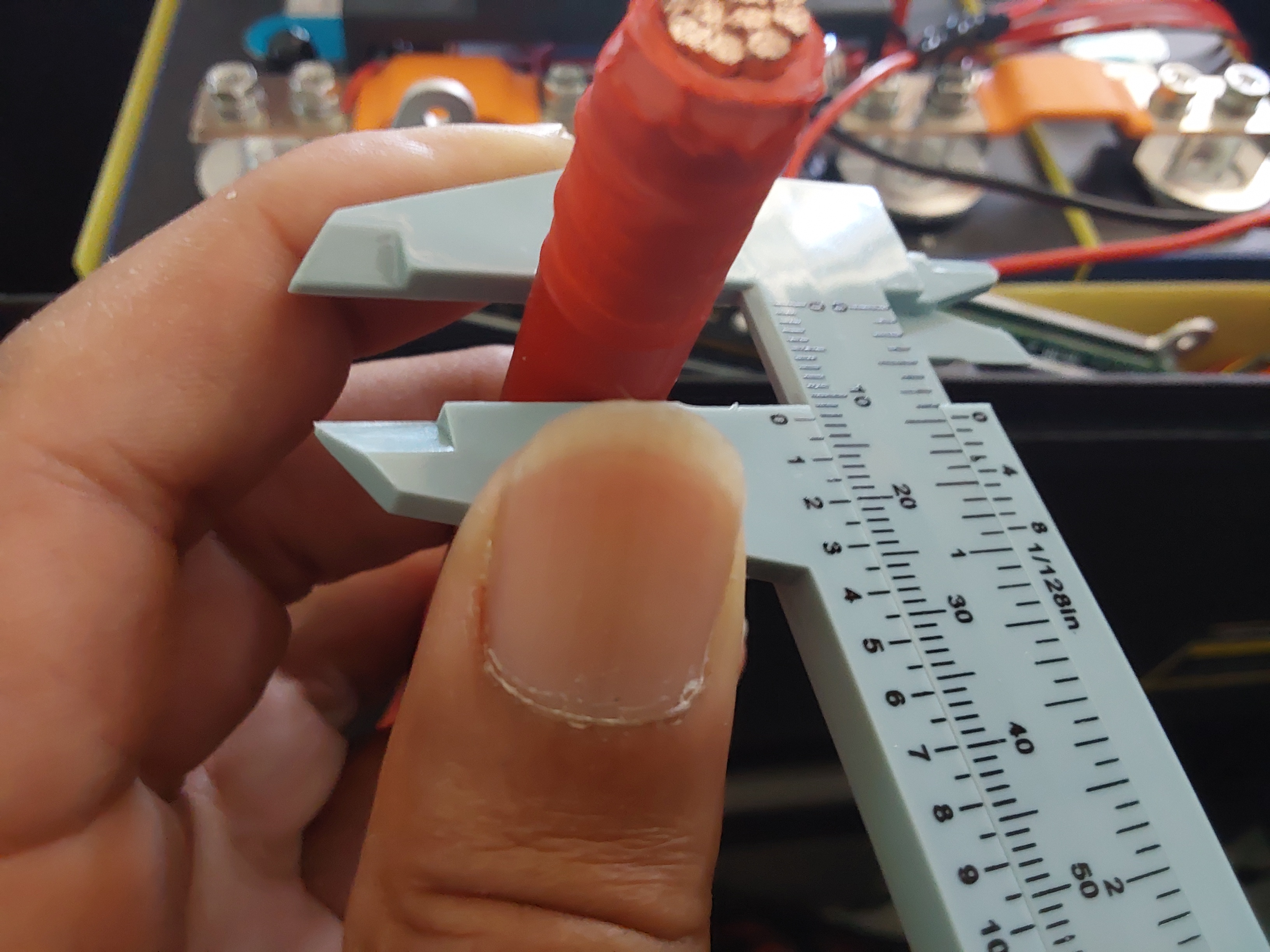
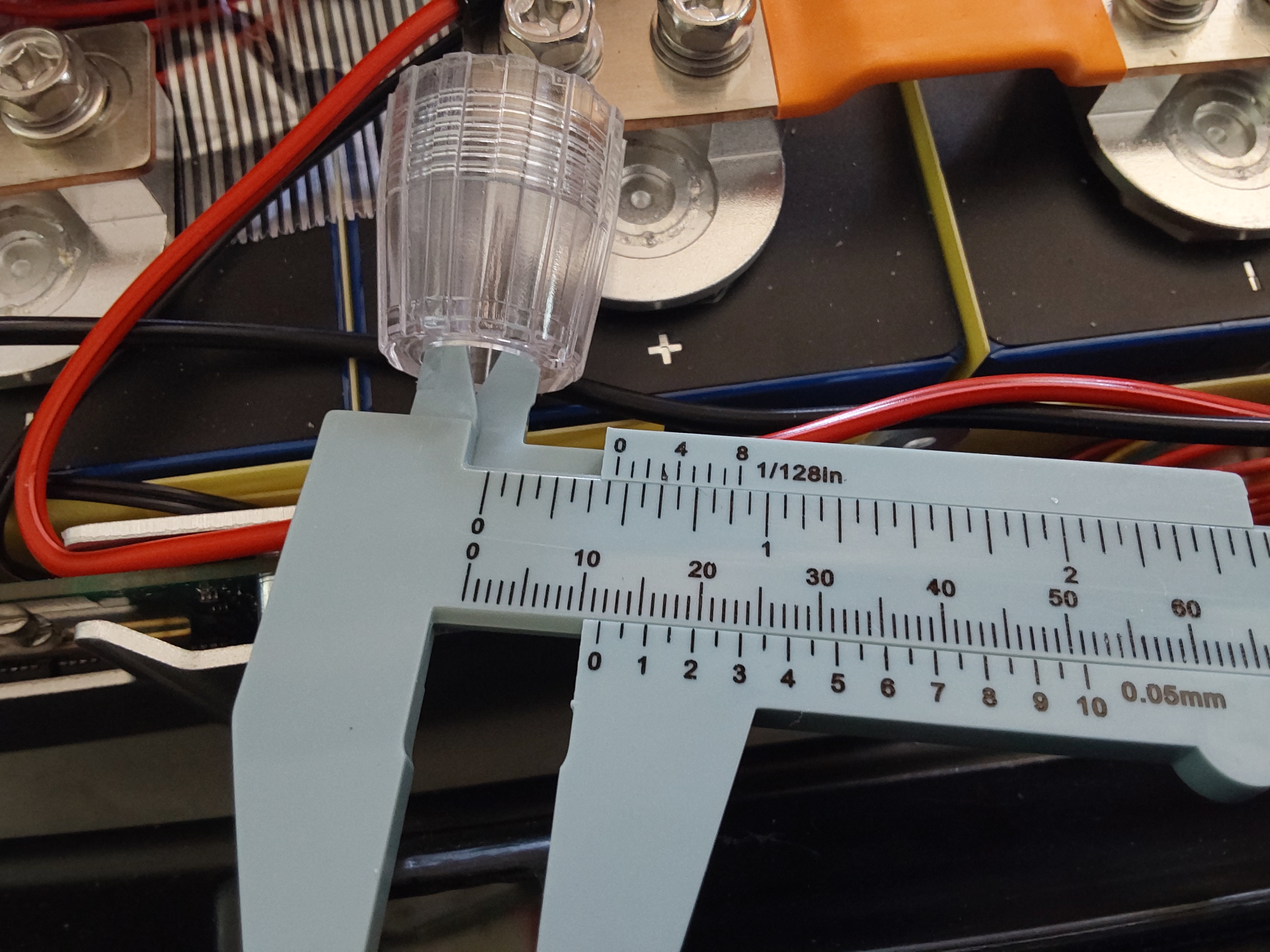
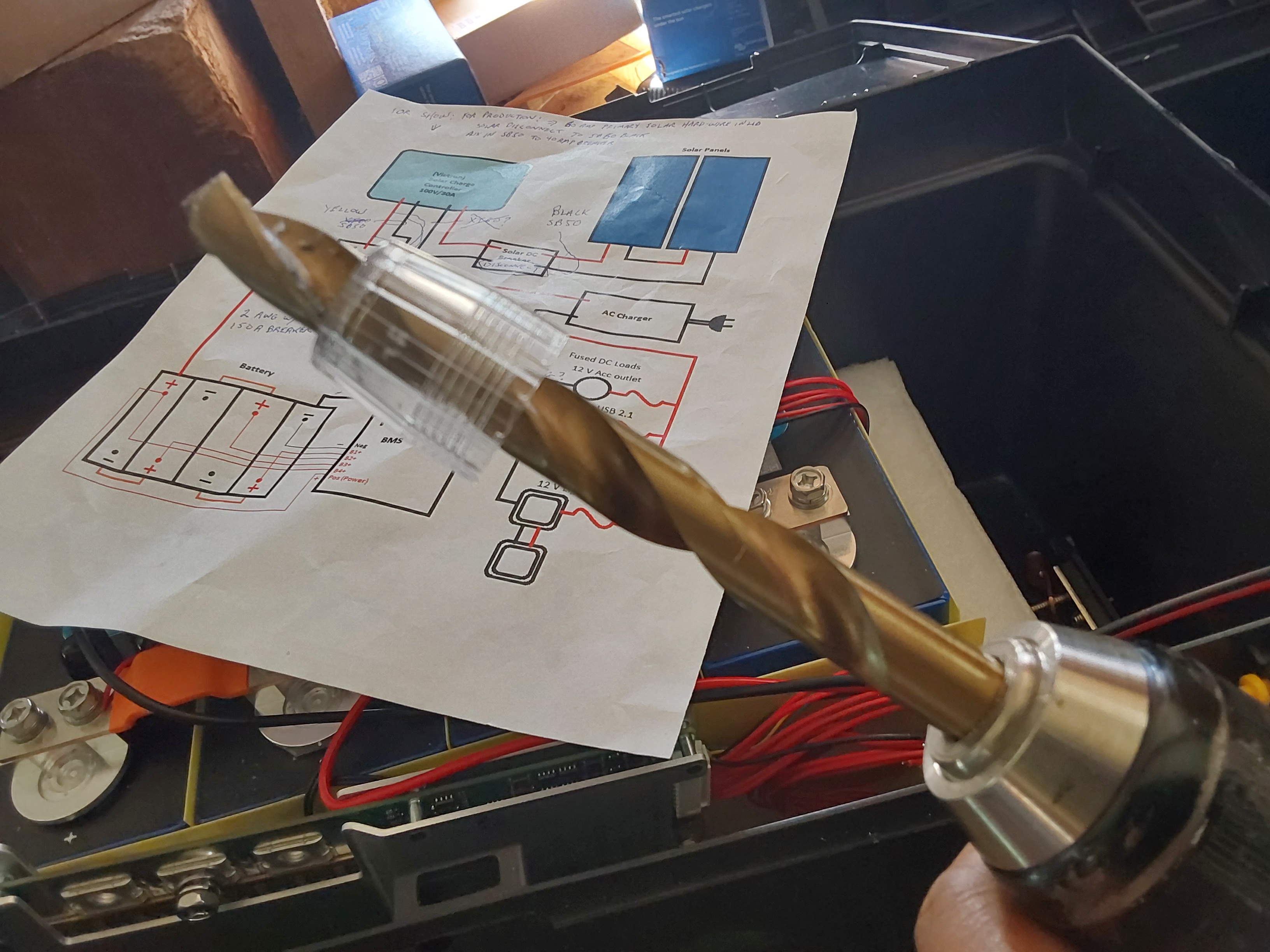
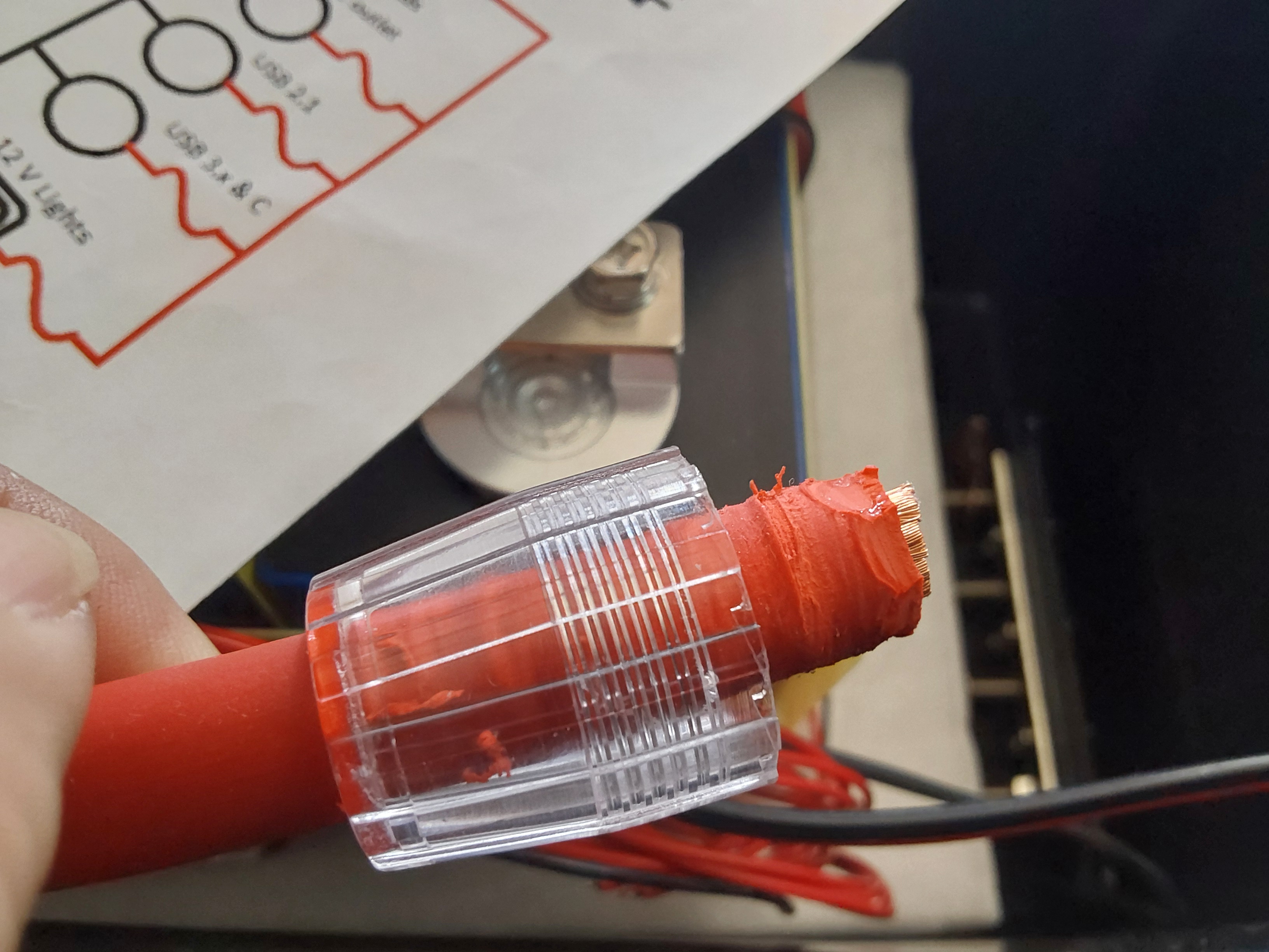
I tried using petroleum jelly and that didn't work, then I tried shaving the end to a taper, and that didn't work very well, so I measured the OD of the cable to be 1/2", and the ID of the cover was about 1/32" too small. I have a 1/2" drill handy, so I drilled it out and it was still a press fit, but it worked so much faster than wrestling with it before.

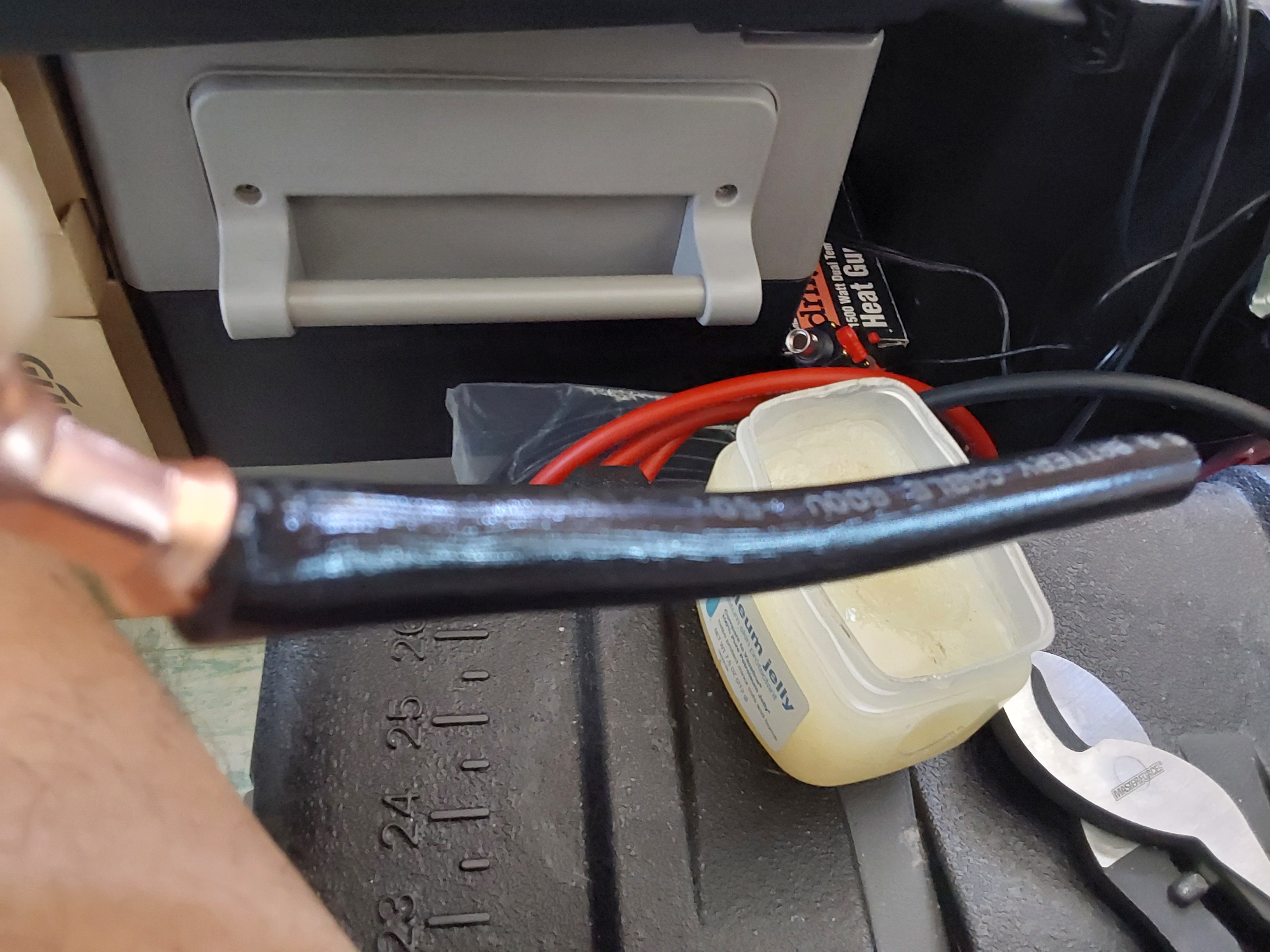
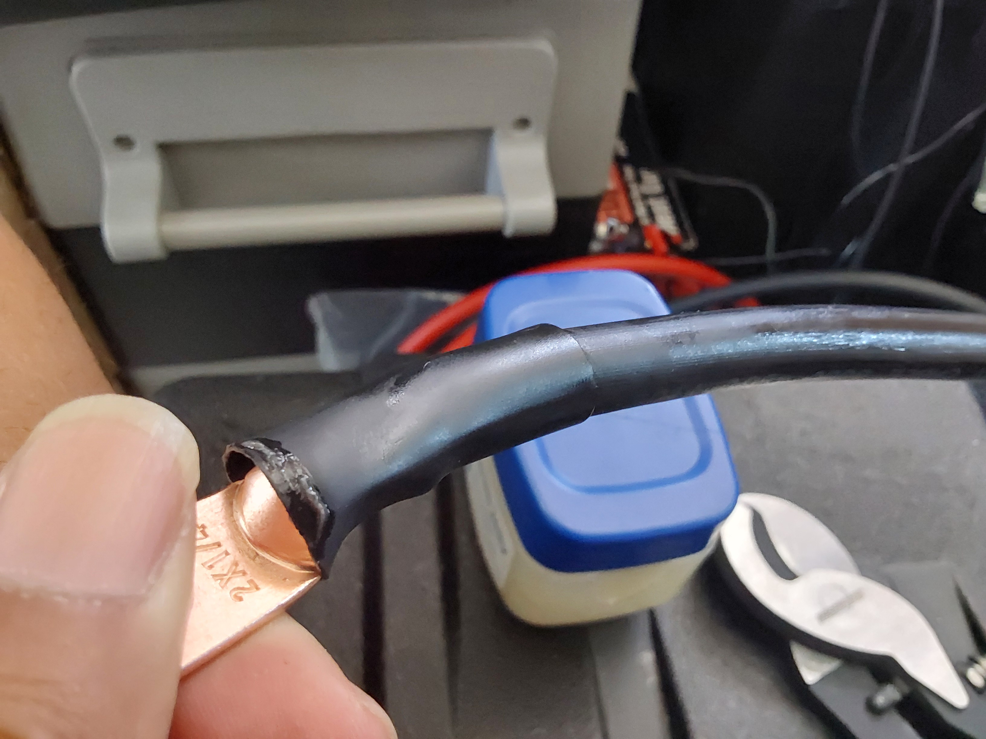
I also found petroleum jelly helped to install the heatshrink tubing much easier, as it's a very close fit to this wire too.
1000011497.jpg
How thick is the cable insulation?
1000011498.jpg
How wide is the opening it needs to get thru? Not enough!
1000011499.jpg
Milwaukee has a great solution!
1000011500.jpg
Much better & faster than before!
1000011493.jpg
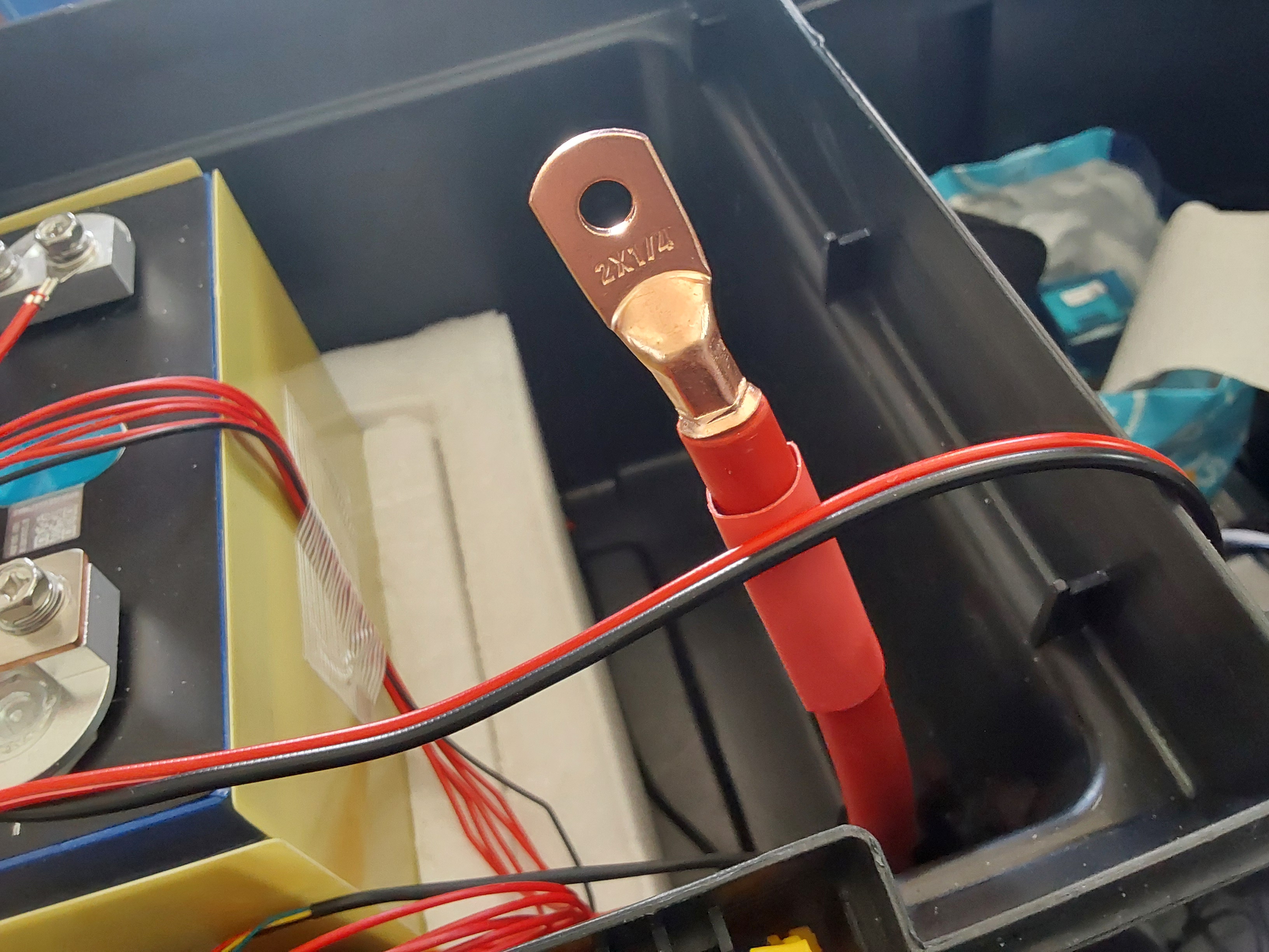
Lubing the cable makes heatshrink easier to get on!
1000011494.jpg
Like this!
Like this!
1000011491.jpg
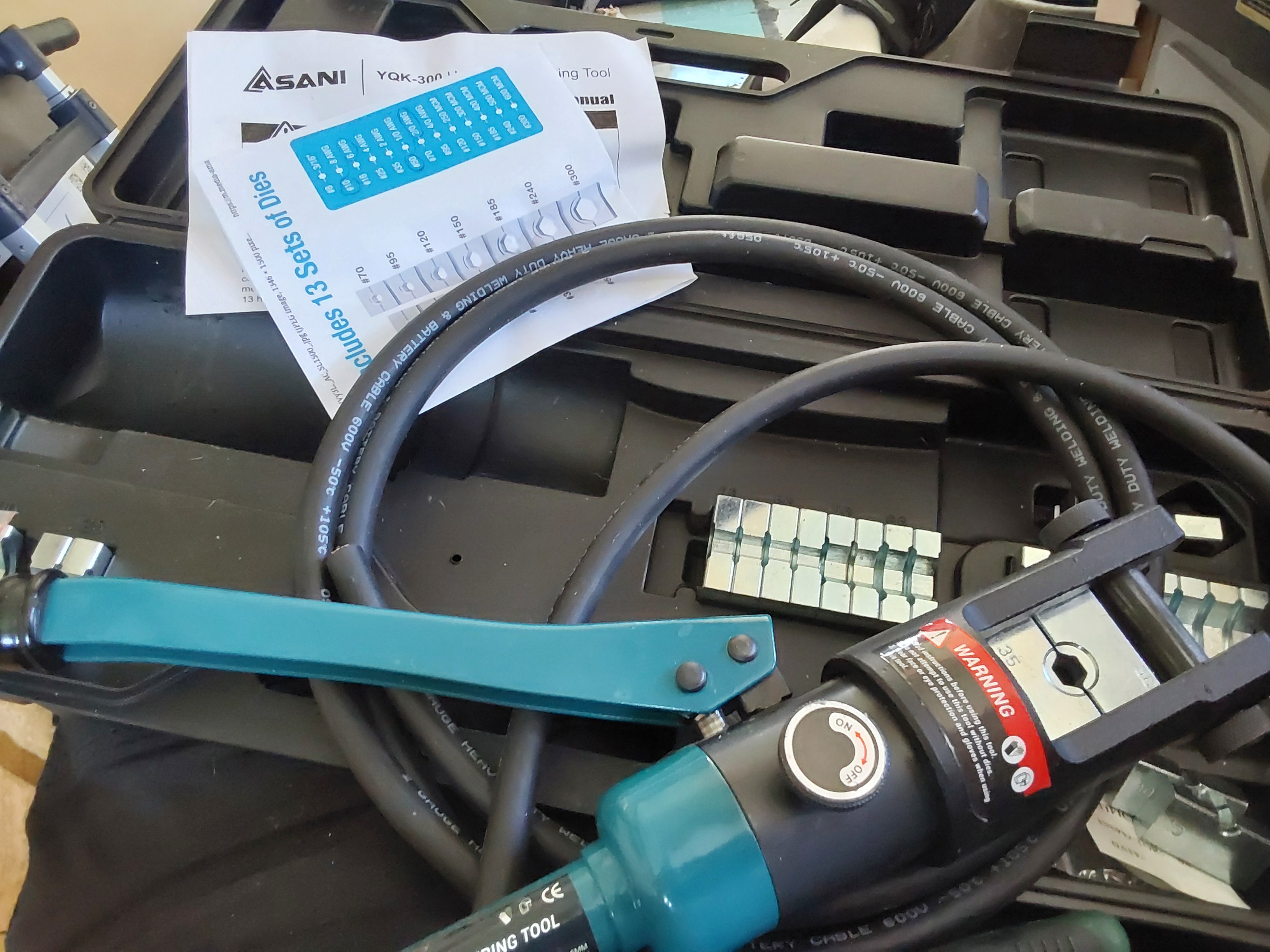
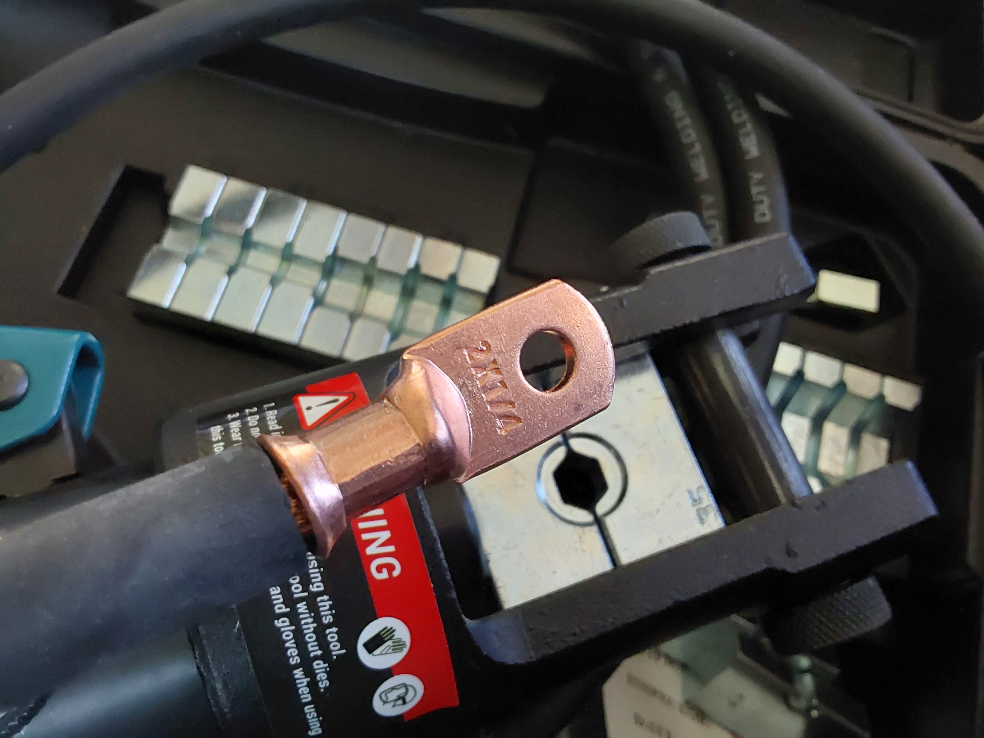
If you are working with larger wire sizes, you probably need one of these
1000011490.jpg
Once you have the correct die size for the terminal lug you can make perfect crimps
1000011496.jpg
Although it takes practice to use it with only 2 hands - it's much easier to use 3 hands (a helper), otherwise you have to brace one handle with your knees...
1000011501.jpg
[Thumbnail for 1000011501.jpg]
1000011495.jpg
[Thumbnail for 1000011495.jpg]
 
Eric Hanson
Steward and Man of Many Mushrooms
Posts: 6145
Location: Southern Illinois
1919
transportation cat dog fungi trees building writing rocket stoves woodworking
  • Likes 6
  • Mark post as helpful
  • send pies
    Number of slices to send:
    Optional 'thank-you' note:
  • Quote
  • Report post to moderator
Allen,

You mentioned cheap MPPT controllers, and I will go one further.  I found out the hard way that there are cheapo, Chinese-made Amazon sold charge controllers that are *Brand Named* “MPPT!”  The actual controller, as you can probably guess by now is actually a PWM controller, but priced about 50% to double the price of its non-MPPT-labeled counterpart.

This really is a case of you get what you pay for!


Eric
 
Allen Jackson
Posts: 137
26
  • Likes 7
  • Mark post as helpful
  • send pies
    Number of slices to send:
    Optional 'thank-you' note:
  • Quote
  • Report post to moderator
Just to be clear, the "cheap" part of many Chinese goods is NOT rooted in their inability to produce high quality products, but is almost ALWAYS tied to the middle-man negotiating for a cheaper product to get a higher commission on the sale - the Chinese factories will do exactly what they were contracted to do and do it well. That being said, there's a lot of importers, who are mostly American business folks, who are making their livelyhood on the difference and betting that the American consumer won't hold them accountable for any problems, especially when they can pass the blame so easily onto the manufacturer...

But there's still a lot of cheap junk available and until the consumer stops buying it, there always will be.

Back on task, Amazon has delivered early and I now have one of the best controllers for this application. For faster charging on this box, it will be both cheaper and safer to use 2 of these in parallel, with 2 solar arrays than it would be to get a single 100 anp charge controller, like the 150 | 100 model.

I also got some 6 AWG battery cable because it's much more flexible than the THHN is, and as it has 105 degree C insulation, it can safely carry more current than the THHN can too.

I even found some breakers that have connections designed for appropriate sized wire.

Unfortunately, it's hot and cloudy today, so not a good day to test the whole setup.
20260517_140653.jpg
The best/cheapest way to maximize your charging!
1000011511.jpg
[Thumbnail for 1000011511.jpg]
20260517_140658.jpg
A better breaker design
1000011510.jpg
6 AWG welding/battery cable
1000011512.jpg
There's room for both of them 🙂
 
Eric Hanson
Steward and Man of Many Mushrooms
Posts: 6145
Location: Southern Illinois
1919
transportation cat dog fungi trees building writing rocket stoves woodworking
  • Likes 2
  • Mark post as helpful
  • send pies
    Number of slices to send:
    Optional 'thank-you' note:
  • Quote
  • Report post to moderator
Fair points about Chinese manufacturing.
 
John Weiland
pollinator
Posts: 2913
Location: RRV of da Nort, USA
896
  • Likes 5
  • Mark post as helpful
  • send pies
    Number of slices to send:
    Optional 'thank-you' note:
  • Quote
  • Report post to moderator
An aspect that I'm still getting my head around....paralleling multiple inverter/chargers in alternative energy set-ups.  Many home inverter suppliers mention being able to parallel daisy chain units for more power or more charge capacity.  This is good stuff to know for those who wish to move slowly into an alt-energy scenario as they can buy conservatively in the beginning, but expand along the way if needs or desires encourage this.  So in your build, Allen, are you placing the output leads of *both* charge controllers on the same input to the battery....positives to positive and negatives to negative....to be able to charge with two arrays of solar?  Do you need to keep the same number/output of solar panels consistent between the two controllers or could one have a bit more or a bit less power coming from the solar panels.  For example, if one of your solar panels gets shade earlier than the other, how is that power difference dealt with by the parallel connection?  ......Perhaps just lower amps from the shaded set coming through its controller versus the sunny set giving higher amps to the total charge profile?
 
Allen Jackson
Posts: 137
26
  • Likes 3
  • Mark post as helpful
  • send pies
    Number of slices to send:
    Optional 'thank-you' note:
  • Quote
  • Report post to moderator
Essentially, yes. Victron also is quite proud of their devices being "networkable", so they can communicate between themselves and I'm going to test that out.

It's my understanding that I'd set one as the master controller and the next/subsequent one(s) would be slaved to it, so the settings would be synced to the master. Even if I can't get that part to work well, I can manually set each to the exact same voltage levels (if I customize them) or just set them to the factory default for LiFePO4 batteries, and like any good lithium battery charger, they should cut out when their charge current drops off to close to zero. That part should still work with any brand of controller with adjustable settings that's compatible with LiFePO4 batteries.

The part about panel configuration is the really nice part - each array need only be compatible with the controller it is connected to, and they are independent of the other arrays, so I can attach (theoretically) one controller with the 50 amp capacity to a 2x2 array of 200 watt panels, one controller with 35 amp capacity can be connected to another pair of Predators in series as a 400 watt array, and a 3rd controller with a 30 amp capacity, can be connected to a pair of 36 Vdc 200 watt panels in either series or parallel, as a separate 400 watt array, and each of them will work to maximize the amount of power produced by each array.

If I had to start from scratch, I'd get 3 of the 50 amp chargers, change my master breaker to 200 amps, and buy more solar panels, because charging at a combined total of 150 amps could completely charge this battery in about 2 hours of sunlight.

That's the ultimately versatile charging configuration, because I probably wouldn't need to deplete the battery each day but I wouldn't have to worry about whether I could charge it up enough to be useful the following day - forever! Add an inverter, and it realistically could run most of a household for an extended time (minus any 240 VAC loads).

The longest we've ever been without power in suburban Chicago, was 3 days, when a fallen tree took down our line to the pole, and because it was on our front yard, the power company wouldn't touch it until we cleared the tree. I had to rent a chainsaw from Home Depot (get in line, there's lots of downed trees in the area), and then get back in line for restoration after clearing it. Something like this would easily be able to run refrigerators and freezers for part of the time and go a long way toward keeping food from spoiling. It's not a complete solution but in a pinch, it gives options.

Ultimately for long-term power indepence/security, I need to build a pergola in the back yard, and put 5-6 Kw of solar panels on it (bypassing the code entanglement of mounting them to the house roof, because ground-mounted arrays are exempted from the module level shutdown requirement), and building another DIY powerwall to use the solar system input as the primary power source and the grid as the backup power.
 
Allen Jackson
Posts: 137
26
  • Likes 3
  • Mark post as helpful
  • send pies
    Number of slices to send:
    Optional 'thank-you' note:
  • Quote
  • Report post to moderator
On a related note, MPPT charge controllers have 2 main specs. The input voltage maximum, and the output current maximum.

Any combination of solar panels on the input side can be used, as long as it doesn't exceed the maximum input voltage (which will likely destroy most charge controllers), but to maximize the output power, the total wattage of the array will need to be closely matched to or exceed the output power of the controller maximum current. For example, my 100 | 30 controller has an upper limit of 100 volts but below that, I can connect 1200 watts of panels (3S2P 24 Vdc panels, running about 63 Vdc and nominally 31 amps) - and still never get much more than 400 watts of charging power (on my 12 volt system), because it maxes out at 30 amps...  Going to a 24 volt system will double the power, but keep the 30 amp limit.

A 35 amp model could be connected to the same solar array, and it should produce about 475 watts because it's limited to 35 amps (for a 12 volt system), but would produce over 900 watts on a 24 volt system. Switching to the 50 amp charge controller, that would produce about 700 watts from the same array, because of the 50 amp limit (on the 12 Vdc system) and 1200 watts on a 24 volt system (now power limited by the solar panels).

If I connect 800 watts of panels to the 700 watt charger, I will get closer to the 700 watt output, with panels left over, and since I would then have 2 different sets of 200 watt panels, I can't combine with each other (the Renogy panels are 36 volt/6.86 amp panels, and the Predators are 24.5 vdc/10.2 amp panels), but I can connect each to a separate controller and add 2 separate 400 watt arrays to maximize my charging at about 105 amps or a bit less (the 35 amp controller won't be maxed out, so it may only produce about 30 amps).

The main battery breaker is a 150 amp breaker and the bus bars and connecting wires are all rated to handle that load (bus bar is rated for 250 amps and the 105 degree C 2 AWG battery cable is rated at 215 amps), so charging at 100 amps (1400 watts) should be able to give me a full charge in just over 3 hrs of full sunlight, unless/until I get more solar panels...

Without changing the solar panels but switching to a 24 volt system will allow me to still charge at 1400 watts using 3 controllers, but only half of the amps, because I've maxed out the panels and can't get more power without more solar panels.

2 of my 200 watt panels aren't as portable-friendly, so I'm not likely to be camping with them, so I really only have 1200 watts of portable camping power, but that still puts me in the "4 hrs to fully charge" zone I was shooting for. By October, when we go to WL, I may have added some more solar panels and the 24 Vdc system I intend to bring will have an 8 KWh battery, so I might want more solar to go with that. It's going to be using the larger 70 amp controller but that requires over 1900 watts of solar panels to max it out, and I don't yet have that many,nor am I convinced that I'll really need it.  More backyard testing through the summer will tell?
 
Allen Jackson
Posts: 137
26
  • Likes 2
  • Mark post as helpful
  • send pies
    Number of slices to send:
    Optional 'thank-you' note:
  • Quote
  • Report post to moderator
Victron's 150 volt charge controllers are also compatible with 36 and 48 volt systems, but the 100 volt controllers are only rated for 12 & 24 volt systems. Something to keep in mind if one is planning to expand later?
 
John Weiland
pollinator
Posts: 2913
Location: RRV of da Nort, USA
896
  • Likes 3
  • Mark post as helpful
  • send pies
    Number of slices to send:
    Optional 'thank-you' note:
  • Quote
  • Report post to moderator
I think this was mentioned further above and don't really want to start a whole new "New life for old inverters" topic.  As I rummaged around over the weekend, I realized that my earlier delving into inverters resulted in the the acquisition of 2 separate 1000W modified sine-wave inverters.  It seems now the general consensus is to use these on a very limited class of powered items.....resistance heaters, incandescent bulbs, single-speed motors, etc.  Just wondering if these should be scrapped or recycled somehow as pure sine wave inverters now seem less expensive than the were 20 years ago....?  Thoughts?.....do others still use these modified sine wave units for dedicated jobs?  Thanks!
 
When I was younger I felt like a man trapped inside a woman's body. Then I was born. My twin is a tiny ad:
grow your own garden and build your own home in the gardening gardeners program
https://wheaton-labs.com/bootcamp
reply
    Bookmark Topic Watch Topic
  • New Topic