gift
Unofficial Companion Guide to the Rocket Oven DVD
will be released to subscribers in: soon!
  • Post Reply Bookmark Topic Watch Topic
  • New Topic
permaculture forums growies critters building homesteading energy monies kitchen purity ungarbage community wilderness fiber arts art permaculture artisans regional education skip experiences global resources cider press projects digital market permies.com pie forums private forums all forums
this forum made possible by our volunteer staff, including ...
master stewards:
  • Nancy Reading
  • Carla Burke
  • r ranson
  • John F Dean
  • paul wheaton
  • Pearl Sutton
stewards:
  • Jay Angler
  • Liv Smith
  • Leigh Tate
master gardeners:
  • Christopher Weeks
  • Timothy Norton
gardeners:
  • thomas rubino
  • Jeremy VanGelder
  • Maieshe Ljin

Concrete Rocket Mass Heater

 
Posts: 21
2
  • Likes 4
  • Mark post as helpful
  • send pies
    Number of slices to send:
    Optional 'thank-you' note:
  • Quote
  • Report post to moderator
I am a long-time lurker, new registrant. I've heard all of Paul's podcasts but I feel like I had been drinking from a firehose. I've been experimenting with various things with various results, but my most unique result is that I have built a rocket mass heater in my workshop using poured concrete as the mass instead of cob. It took months of experimentation and construction, but I believe I have something that is unique and will keep my shop warm through the winter.

Unfortunately, I just did the last pour yesterday and it's warming up so I will have to wait until next winter to see if it works as designed, but the initial test results are encouraging.

The project, in bullet points:

  • workshop is three 40-ft shipping containers welded together.

  • R-19 insulation in roof covered with rubber roofing

  • 2" rigid foam insulation in walls, covered with 1/2" sheetrock

  • Rocket mass heater runs along the 40' back wall

  • 8" system with fire brick for J-channel

  • 35-gal drum containing pearlite insulation

  • 55-gal drum for outer containment

  • Concrete mass is 15" deep and 20" high

  • Every four feet has two 8x8x16 concrete blocks to allow flow of cool floor air through the mass

  • (here's the cool part) Every four feet I have embedded a digital thermometer (DS1820) in the concrete. All sensors are hooked to an Arduino-based control unit that uploads the temperature of 15 sensors every minute for real-time monitoring of the entire heater

  • In addition to the embedded sensors, there is an infrared sensor pointed at the top of the drum and a second infrared sensor pointed at the outside of the combustion chamber. Plus a sensor for outside temperature, a sensor about a foot from the exit of the exhaust chimney, and one for the ambient air temperature inside the shop.

  • I have written a PHP program that reads the database and shows the temperature of all sensors graphically as the day progresses


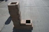
    • So that's my project. I have a ton of pictures and a few videos showing the progress. I've attached a picture of the core with the inner drum as we weld the two barrels together to collect the pearlite. You can see the fire brick that creates the J-channel and the 8" vent and the concrete forms. I've also attached a graph of a test burn that was performed before all of the concrete was poured.

      There are some lessons learned and some things I would do differently the next time. I'm willing to share if anyone is interested in my experiences with an alternative to the cob-based rocket mass heater.


130322-IMG_20130322_172236_242.jpg
welding barrel for rocket mass heater
Welding the inner drum
RMH-2013-04-16.png
an Arduino-based control unit uploads the temperature of 15 sensors every minute for real-time monitoring of the entire rocket mass heater
Concrete Rocket Mass Heater embedded sensor graph
 
pollinator
Posts: 4154
Location: Northern New York Zone4-5 the OUTER 'RONDACs percip 36''
67
hugelkultur fungi books wofati solar woodworking
  • Mark post as helpful
  • send pies
    Number of slices to send:
    Optional 'thank-you' note:
  • Quote
  • Report post to moderator
Baxter T. : W.O.W., all I can say is a Big Welcome to PERMIES, and the Permies Rocket Stove Forum/Threads! The sensors are a thing that has been talked to death
without anyone actually doing any thing about it ! If you had to duplicate the sensors and the arduino system to make it compatible with a lap top what do you think it
would cost?

After I have a chance to take this all in, I will probably be back with a dozen questions ! Again just as one member to another welcome. For the Craft! Pyro AL
 
gardener
Posts: 1057
Location: +52° 1' 47.40", +4° 22' 57.80"
448
woodworking rocket stoves wood heat
  • Likes 1
  • Mark post as helpful
  • send pies
    Number of slices to send:
    Optional 'thank-you' note:
  • Quote
  • Report post to moderator
Baxter, welcome to the forum.
I would like to know some more details.

Like the total length of the bench run, and what your chimney is like.

Since you've used two smaller drums for the inner barrel how have you solved the height difference with the outer barrel? Utilizing 1.5 drums of 55 gallon apiece perhaps?

Is the bench the only part that's embedded in concrete or the feed and burn tunnel as well? Insulation around the hottests parts and what kind of?

I'd imagine the connection between the steel drum and the concrete bench would crack, how did you solve that?

Any idea of the total weight of this rocket mass heater? That would be a lot of mass, I'd think, cob isn't as dense as concrete.

regards, Peter
 
Posts: 604
56
5
  • Likes 1
  • Mark post as helpful
  • send pies
    Number of slices to send:
    Optional 'thank-you' note:
  • Quote
  • Report post to moderator
These readings imply that, using an 8" system, only the first 8-10 feet of the mass channel takes 90+% of the heat load; as the temp readings for the remainder of the mass sensors is not much different than the exit temp any any time along the firing cycle. Intuitively, the first several feet would be crucial, but I wouldn't have expected the temps to flatten out quite so dramaticly.
 
allen lumley
pollinator
Posts: 4154
Location: Northern New York Zone4-5 the OUTER 'RONDACs percip 36''
67
hugelkultur fungi books wofati solar woodworking
  • Mark post as helpful
  • send pies
    Number of slices to send:
    Optional 'thank-you' note:
  • Quote
  • Report post to moderator
Baxter T.: These temperatures seem low, I'm wondering about the exit speeds of the hot exhaust gases! How long is the bench, and how high is the chimney!
You say its an 8'' system, what size is the flue size of the chimney ! What sized cap if any ! Eagerly awaiting new pictures !

For the craft ! be safe, keep warm! PYRO Logically Big Al Open for all comments !
 
Baxter Tidwell
Posts: 21
2
  • Likes 1
  • Mark post as helpful
  • send pies
    Number of slices to send:
    Optional 'thank-you' note:
  • Quote
  • Report post to moderator
I estimate that the total weight of the bench is 7,500 pounds. That's calculating the weight of the concrete at 145 pounds per cubic foot. Add another couple hundred pounds for the concrete blocks that act to get the cold floor-level air to pass by the bench.

The bench is about 35 feet long. It's a straight run, exiting the mass straight up, and then two 90's to get outside. The outdoor chimney is five feet long with a simple rain cap on it. I agree that the exit temperature seems high. I can think of three reasons for this. First, the probe is about a foot inside the top of the chimney. So it'll read a bit hotter than directly at the end of the exhaust. Second, these temperatures were read when there was only about five feet of bench mass, and that was at the beginning. The uncovered vent for the rest of the run was very hot. I would assume that when the entire mass is in place, the temperature will be a lot cooler. Third, this run was done when the outside temperature was around 50 degrees. Not a temperature that you'd run such a beast. I would suspect that, once winter comes again, the mass would suck up even more of the heat.

There is a gap between the outer barrel and the concrete. I didn't want to go against the drum with concrete as the type of concrete I was using tends to fail at around 600 degrees. I was planning on covering that with high-temperature fire clay, but I'll probably just leave it open.

I wanted to get the stack as high as possible, so I made it as high as I could while still being able to fit the 55-gal drum on. Remember that the workshop is a shipping container and I'm restricted to an 8-ft ceiling. I did a lot of grinding and welding to put the four barrels together. There's a two-inch gap between the top of the riser and the top of the top barrel.

I'll post some pictures as soon as I can sort through them. Perhaps that would make things clearer.
 
pollinator
Posts: 4715
Location: Zones 2-4 Wyoming and 4-5 Colorado
492
3
hugelkultur forest garden fungi books bee greening the desert
  • Mark post as helpful
  • send pies
    Number of slices to send:
    Optional 'thank-you' note:
  • Quote
  • Report post to moderator
Baxter, welcome to permies! Thanks for sharing your info!
 
Posts: 8
Location: Centurion, South Africa
  • Mark post as helpful
  • send pies
    Number of slices to send:
    Optional 'thank-you' note:
  • Quote
  • Report post to moderator
Hi Baxter

This is a very cool project you have going here. I love the fact that you are using your Arduino as well! Suddenly I have a few new idea for mine! I am at the point of building my heat battery and was playing with the idea of using concerete. So this might be the solution afterall! Would love to see the pictures and videos of how you did the bench.
 
Peter van den Berg
gardener
Posts: 1057
Location: +52° 1' 47.40", +4° 22' 57.80"
448
woodworking rocket stoves wood heat
  • Likes 1
  • Mark post as helpful
  • send pies
    Number of slices to send:
    Optional 'thank-you' note:
  • Quote
  • Report post to moderator

Baxter Tidwell wrote:The outdoor chimney is five feet long with a simple rain cap on it. I agree that the exit temperature seems high. I can think of three reasons for this. First, the probe is about a foot inside the top of the chimney. So it'll read a bit hotter than directly at the end of the exhaust. Second, these temperatures were read when there was only about five feet of bench mass, and that was at the beginning. The uncovered vent for the rest of the run was very hot. I would assume that when the entire mass is in place, the temperature will be a lot cooler.


The exit temperature is already quite low in fact. Everything lower than 90 degrees F. could result in vapour condensation. This has only partly to do with the moisture of the wood. In fact even 100% dry wood will produce about 60% of it's own weight as water. Combustion of wood do produce heat (obviously) CO2 and water, about the same way as natural gas will.

In time, with all the mass in place the exhaust temps will rise. That's because the bare duct will dissipate the heat a lot quicker than the mass can absorp it. So your graph will change, probably the temps will even out more than at the state which is reflected by the graphic. A covered bench will behave very different as compared to a thin-walled horizontal stove pipe.

Baxter Tidwell wrote:There is a gap between the outer barrel and the concrete. I didn't want to go against the drum with concrete as the type of concrete I was using tends to fail at around 600 degrees. I was planning on covering that with high-temperature fire clay, but I'll probably just leave it open.


When it's not leaking it would work like this. Do you have a CO alarm at hand?

Baxter Tidwell wrote:There's a two-inch gap between the top of the riser and the top of the top barrel.


That gap should be the minimum value, hopefully the top of the heat barrel won't buckle in.

regards, Peter
 
Baxter Tidwell
Posts: 21
2
  • Likes 1
  • Mark post as helpful
  • send pies
    Number of slices to send:
    Optional 'thank-you' note:
  • Quote
  • Report post to moderator
For this chart, only the first two sensors were actually embedded in the concrete. The rest were just sitting at their positions where they will eventually be embedded. That's why they all reported pretty much the same temperature, which is the air temperature near the horizontal bench.

When I said "gap", I meant a gap between the concrete and the stove. The gasses are locked up tight (hopefully) in the venting.

I've attached pictures that show the state of the heater when the first test firing was done. Only the first two sensors were embedded and the rest were just laying around.
IMG_20130413_122914.jpg
rocket mass heater build in progress
A view down the form towards the core
IMG_20130413_120036.jpg
rocket stove exit flue
Exhaust end with cleanout
IMG_20130413_104128.jpg
rocket heater with concrete mass construction
The core and the first concrete pour.
 
Baxter Tidwell
Posts: 21
2
  • Mark post as helpful
  • send pies
    Number of slices to send:
    Optional 'thank-you' note:
  • Quote
  • Report post to moderator
I started a separate thread for discussions about the embedded temperature sensors and the Arduino microcontroller: https://permies.com/t/24654/rocket-stoves/Temperature-Sensors-Rocket-Mass-Heater
 
Posts: 26
  • Mark post as helpful
  • send pies
    Number of slices to send:
    Optional 'thank-you' note:
  • Quote
  • Report post to moderator
Baxter thats a extremely nice job!
Im a little jealous, I can see the thought and work you put into this, congratulations!
I have a question, where does your fresh air come from?
This isnt a critique, just a question.
Congratulations again, im sure your shop/space will be a masterpiece of detail and organization!
And warm all winter long!
Jon
 
Baxter Tidwell
Posts: 21
2
  • Mark post as helpful
  • send pies
    Number of slices to send:
    Optional 'thank-you' note:
  • Quote
  • Report post to moderator

Jon Kennedy wrote: I have a question, where does your fresh air come from?


Fresh air is no problem, unfortunately. The shop is three 40-ft steel shipping containers welded together. It is very difficult to get everything air-tight, especially around doors and windows. There's always a draft somewhere.

But that's not a problem because it's a workshop, and you'd expect it to be drafty. Maybe this winter I'll want to seal it up a bit more if it's uncomfortable. If that causes a constriction in airflow, perhaps I can punch a hole in the outside wall next to the heater core and let in some fresh air. I'll figure it out as I go along.

When I build a RMH in the house next year, I'll have to deal with that question. I have some ideas, but I'll have to do some more research and experimentation.
 
pollinator
Posts: 1481
Location: Vancouver Island
60
  • Mark post as helpful
  • send pies
    Number of slices to send:
    Optional 'thank-you' note:
  • Quote
  • Report post to moderator

Baxter Tidwell wrote:

Fresh air is no problem, unfortunately. The shop is three 40-ft steel shipping containers welded together. It is very difficult to get everything air-tight, especially around doors and windows. There's always a draft somewhere.

But that's not a problem because it's a workshop, and you'd expect it to be drafty. Maybe this winter I'll want to seal it up a bit more if it's uncomfortable. If that causes a constriction in airflow, perhaps I can punch a hole in the outside wall next to the heater core and let in some fresh air. I'll figure it out as I go along.

When I build a RMH in the house next year, I'll have to deal with that question. I have some ideas, but I'll have to do some more research and experimentation.


First time I have seen this thread, so my reply is a bit late. As discussed elsewhere, I prefer air supply to come from the room after the people have had a chance at it, so I would want the fresh air coming in from the opposite end of the building (running through the heat mass if needed to not be chilled). A wood heated building is a "living system" first and heated box second so long as it does not interfere with the first.

Re. Temperature measurement. It is perfectly reasonable to measure mass temperature, but the exhaust probe is measuring gas stream and so will seem higher than would be expected. Experiments with measuring centre of flue (a probe to gas stream centre with a plate to collect the heat) shows a higher temperature than the surface of the surrounding flue. Again, there is nothing wrong with measuring this way. One does have to remember to take this into account is all, when looking at the data. Data collection is something I would like to do a lot more of. I would like to include air temp., and a "black body" placed in various places to measure radiated heat gain (and loss from the back side ). I would like to see how heat reflectors would affect things too. Heat radiated to roof (for example) could be reflected down to where it could do some more good, or angled to hit people's backside. As a bonus these surfaces might disperse sound waves for a less "ringy" room.
 
Posts: 2
  • Likes 1
  • Mark post as helpful
  • send pies
    Number of slices to send:
    Optional 'thank-you' note:
  • Quote
  • Report post to moderator
Hi Baxter, any chance of an update to this thread?  I'd love to see the finished product, and also a chart with all the mass in place.
 
Posts: 3
  • Likes 1
  • Mark post as helpful
  • send pies
    Number of slices to send:
    Optional 'thank-you' note:
  • Quote
  • Report post to moderator

Baxter Tidwell wrote:

Fresh air is no problem, unfortunately. The shop is three 40-ft steel shipping containers welded together. It is very difficult to get everything air-tight, especially around doors and windows. There's always a draft somewhere.

But that's not a problem because it's a workshop, and you'd expect it to be drafty. Maybe this winter I'll want to seal it up a bit more if it's uncomfortable. If that causes a constriction in airflow, perhaps I can punch a hole in the outside wall next to the heater core and let in some fresh air. I'll figure it out as I go along.


Baxter, a couple of things for ya,
Maybe you've already done it, but putting in a dedicated fresh air intake (in HVAC they call it combustion air) is a great idea for a couple of reasons.
(I'm actually in the HVAC service industry, so I'm kindof a traitor for being here 😛 but this stuff is fascinating)
1. Being that your shop is already drafty, when you fire that thing up it's got to pull that fresh, cold air thru the cracks and crevices and thru your shop to get to the RMH, further chilling your shop along the way.
2. Your heater will be more efficient for 2 reasons. First reason going back to #1. Your not heating the "combustion air" as it travels thru the shop.
#2 colder air causes a more efficient burn. I'm not real sure of the science behind this, but it's something about denser air, more available oxygen, blaah, blaah, blaah.....

But yea, in the drafty shop, if it's possible put one in. Make it as close to the intake of the RMH as possible, if not directly into it sealed up and everything.
 
pollinator
Posts: 3847
Location: Marmora, Ontario
593
4
hugelkultur dog forest garden fungi trees rabbit urban wofati cooking bee homestead
  • Likes 2
  • Mark post as helpful
  • send pies
    Number of slices to send:
    Optional 'thank-you' note:
  • Quote
  • Report post to moderator
I would love an update to this thread. Any chance of a graph like the first with your completed system? Maybe at set intervals throughout a season with your regular burn regimen?

-CK
 
Posts: 11
  • Mark post as helpful
  • send pies
    Number of slices to send:
    Optional 'thank-you' note:
  • Quote
  • Report post to moderator
Hi Baxter.
I would love an update on this please.
I’m about to create a similar set-up with the mass being the concrete floor. However, I’m worried the differential temperatures will cause the concrete floor to crack.
Have you experienced any cracking of the concrete?
 
Posts: 1
  • Mark post as helpful
  • send pies
    Number of slices to send:
    Optional 'thank-you' note:
  • Quote
  • Report post to moderator
Sink the J-Chanel and put the heat exchanger piping in a concrete floor?  You have the floor anyway.

I know it works with electric resistance cables embedded  in concrete floors. - Why not rocket heater exhaust ducts?
 
Posts: 66
7
  • Likes 2
  • Mark post as helpful
  • send pies
    Number of slices to send:
    Optional 'thank-you' note:
  • Quote
  • Report post to moderator

allen lumley wrote: Baxter T. : W.O.W., all I can say is a Big Welcome to PERMIES, and the Permies Rocket Stove Forum/Threads! The sensors are a  thing that has been talked to death
without anyone actually doing any thing about it ! If you had to duplicate the sensors and the arduino system to make it compatible with a lap top what do you think it
would cost?

After I have a chance to take this all in, I will probably be back with a dozen questions ! Again just as one member to another welcome. For the Craft!  Pyro AL


I saw this, and yes it is old.

The sensor thingie is not that difficult, I have old LPG boxes what use a servo and a lambda sonde for measuring oxygen in output gasses
and do regulate to get as less as possible what confirms good combustion's.

the stepmotor can be change for a valve step system so the computer can regulate the air input.

regards

 
I agree. Here's the link: https://woodheat.net
reply
    Bookmark Topic Watch Topic
  • New Topic